Thank you for choosing the Biomega BioClave Mini steam sterilizer. Your steam sterilizer has been CE certified and designed with durability, reliability, and safety in mind. It is your responsibility to install this instrument in conformance with local electrical codes. This manual contains important operating and safety information. Please read and understand the contents of this manual prior to operating this instrument.
TABLE OF CONTENTS 1. GENERAL ------------------------------------------------------------ 1 2. TECHNICAL SPECIFICATIONS----------------------------------- 2 3. PACKING CONTENT ----------------------------------------------- 3 4. INSTALLATION ---------------------------------------------------- 4 5. CONTROL PANEL --------------------------------------------------- 5 6 . OPERATION --------------------------------------------------------- 6 6.
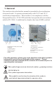
1. General The sterilizer described in this manual is intended for the sterilization of research tools. It operates automatically with 134°C and 121°C sterilization temperatures. This sterilizer is in compliance with the European Directive 93/42/CEE and it has been produced in accordance with the EN 13060. In addition the chamber has been ASME certified.
2. Technical Specifications (1) Chamber Dimensions: 6.7in. x 12.6in. / 170mm x 320mm (2) Rated Voltage: AC110V-120V or 220-240V, 50-60Hz (3) Nominal power: 1300 W (120V) 950W(220V) (4) Sterilization Temperature: 121°C / 134°C (5) Main Fuses: T20A/ T12A/250V (6) Capacity of the distilled water tank: Approx 2.5L (water at level MAX) (7) OperatingEnvironment: 5 - 40°C (8) External Dimensions: 13.5in. (width) x 13.4in. (height) x 20.1in.
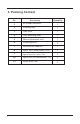
3.
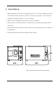
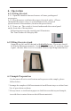
4. Installation * Ensure that the sterilizer is installed with 2.5in. (10cm) ventilation space on all sides of the sterilizer, and 5 in. (20cm) on top side. The clearance required to open the door is 15.5in. (40cm). * The sterilizer should be placed on a level worktable. * Do not cover or block the door, ventilation or radiation openings on the sterilizer. * Do not install the sterilizer near a sink or in a location where it is likely to be splashed. * Do not install the sterilizer nearby a heat source.
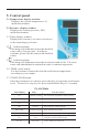
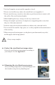
5. Control panel 5.1 Temperature display window. Displays the current temperature(°C) inside the chamber. 5.2 Pressure display window . Displays the current pressure ( PSI) inside the chamber. 5.3 Timer display window Displays the current cycle state (see below) or the remaining cycle time. 5.4 Indication lamp This lamp will illuminate when the distilled water tank is low on water. In order to continue, please fill this tank (with distilled water). 5.
6. Operation 6.1 Getting Started 6.1.1 Open the chamber door and remove all inner packing and accessories. 6.1.2 Plug the power cord into the proper electrical outlet. (Please check that the power source is in accordance to the electrical specifications of the machine (listed on the power label). 6.1.3 Power on - The switch is located underneath the control panel on the front side of the machine. Following power up, the control panel illuminates. The Time window will display Ld . 6.
* Verify all samples are not sealed, capped or closed. * Do not overload the trays above the stated limit (see Appendix 1). * Do not stack the trays one above the other or put them in direct contact with the walls of the sterilization chamber. * When handling the trays, always use the tray removal tool. * Wrap each sample separately, if samples are wrapped together verify that they are of the same material. * Seal the wrap with sterilization adhesive ribbon or by a thermal sealer.
6.6 After the samples are loaded, close and lock the door by turning the door handle clockwise until it stops. Caution: You must turn the door handle to the maximum position, otherwise the machine will alarm and an error message will be displayed during the cycle. 6.7 Start the sterilization program. Press START button - the machine will start the cycle. The cycle will take 12-55 minutes.
7. Draining the water tanks 1. Connect the supplied drain hose to the drain valve by pressing it on firmly. 2. Set the drain valve to the open position by turning it counter clockwise 4. After you have completed draining the water, push the drain valve inward and tank will begin to drain through the hose. set to the closed position 3. Pull the drain valve outward, the The sterilizer includes two draining valves. The left valve is used for draining the used water tank.
8. Maintenance 7. Maintenance Frequency Daily Weekly Annually Operation Clean the door seal Wipe dry the inner chamber Clean the clean water tank Clean the inner-chamber Replace the door seal 8.1 Cleaning the door seal Clean the door seal daily with a softy cloth saturated in distilled water 8.2 Cleaning the clean water tank Clean the clean water tank every week with medical disinfectant .
8.3 Cleaning the inner-chamber, weekly - Remove the trays and tray rack from the inner-chamber - Wipe the inner chamber with a soft cloth saturated in distilled water - Apply the same procedure to the trays and tray rack. 8.4 Door adjustment Below are the instructions for the door adjustment. This should only be performed if the door is not providing the proper seal or if the door seal has just been replaced. 8.4.1 Open the door and insert the door adjustment tool in the gap beneath the plastic cover (Fig.
8.5 Replacement of the door seal 8.5.1 Fully open the door. 8.5.2 Remove the door seal carefully by pulling it by hand away from the door 8.5.3 Clean the new door seal carefully with a soft cloth saturated with distilled water. 8.5.4 Moisten the new seal with medical disinfectant . 8.5.5 Insert the new seal following the instruction below: 1). Press on the top of the seal. 2). Press on the bottom of the seal. 3). Press on the left and right portions of the seal. 4).
8.6 Replacing the power fuse 1). Switch off the power. 2). Push inward with a flat head 3). Pull out the fuse holder by screw driver, then unscrew the fuse hand. holder ( counter clockwise). 4).Replace the fuse with a fuse of the proper electrical requirements (see pg.2). . 5). Place the fuse holder back in place and use a flat head screw driver to fully push it in. Then tighten (clockwise). 9 Transport and Storage 9.1 Switch off the sterilizer before transportation or storage.
10. Error Codes Code 14 Description Proposed solution E1 Inner temperature sensor error E2 Temperature sensor of chamber Check temperature sensor of chamber wall error wall E3 Failure to rise temperature Check water pump or the door seal E4 Failure to release the steam Check the air release valve E5 Door is opened during the cycle Make sure you have turned the door handle to the max.
11. Service and contact For additional information on any of the error codes listed in section 10, please contact your sales representative, or contact Biomega Research Products Service Department at 1-908-769-5555. Please have the unit’s serial number (located on the back panel of the instrument) available when calling. Do not send in a unit for service without first calling to obtain a repair authorization number and a decontamination form. The unit should be properly packed to avoid damage.
APPENDIX 1 Water Properties/Characteristics: DESCRIPTION WATER CONDENSATE Evaporate residue 。10 mg/l 。1.0 mg/kg Silicium oxide sio 2 。1 mg/l 。0.1 mg/kg Iron 。0.2 mg/l 。0.1 mg/kg Cadmium 。0.005 mg/l 。0.05 mg/kg 。0.05 mg/l 。0.1 mg/kg 。0.1 mg/l 。0.1 mg/kg Chloride 。2 mg/l 。0.1 mg/l Phosphates 。0.5 mg/l 。0.1 mg/l Conductivity (at 20。) 。15ヲs/cm 。3ヲs/cm Lead Rest of heavy metals, excluding iron, cadmium, lead pH value Appearance Hardness Instructions manual 5-7.
APPENDIX 2 30 10 20-25 Unwrapped hollow material 5.00 121 16 20 30-35 Single-wrapped solid material 4.00 Total Cycle Time (min.) Pressure (PSI) 134 Sterilization Time (min.) Temperature (C) MAX. LOAD (k.g) DIAGRAM: STERILIZATION PROGRAMS TYPE The max. temperature of the 134 C sterilization cycle is 136C The max. temperature of the 121 C sterilization cycle is 123C Pressure PSI £ a 134 C Pressure £PSI bar £ 121C 30 15 0.0 -10 30 15 0.
APPENDIX 3 ELECTRICAL DRAWING ¡ 21V ¡ 11V V1 V2 WATER PUMP FAN AC220V OUTPUT TANK MAX. LEVEL PUBLIC TANK MIN.
APPENDIX 4 Diagram :Hydraulic Drawing Safety valve Pressure sensor Pump Condenser Chamber Distilled water tank Used water tank V1: Air/Steam release valve V4: Water release valve 19 Instructions manual