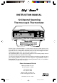
Digi –Sense ® INSTRUCTION MANUAL 12-Channel Scanning Thermocouple Thermometer MENU °F EXIT +ALARM 1 STORE 2 LOG 3 RECALL 4 PRINT 5 MAX 6 MIN 7 AVG 9 SCAN 8 HOLD 0 CLEAR Model Nos. 69200-00 Benchtop 115V 69202-30 Benchtop 230V Each of the up to 12 thermocouples is scanned once every four seconds to once every hour (settable). The current readings are displayed on the large liquid crystal display. Readings that exceed a maximum or minimum value can be set to trigger an alarm.
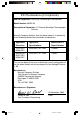
EU Declaration of Conformity Name of Apparatus: Scanning Thermocouple Thermometer Model Number: 69202-30 Description of Apparatus: 12-Channel Benchtop Thermocouple Scanner Barnant Company declares that the above model is in conformity to the following harmonized standards and directives: Applicable Directives Applicable Specifications Manufacturer’s Report Number 73/23/EEC 93/68/EEC EN61010-1/A2: 1995 TR9866 89/336/EEC 92/31/EEC 93/68/EEC EN61326-1/A1: 1998 TR9867 The last two digits of the year i
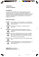
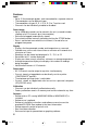
Introduction Safety Precautions Introduction This Scanning Thermocouple Thermometer continuously monitors temperatures at up to 12 locations. It is designed for laboratory or industrial applications for unattended temperature monitoring. An alarm is set off when any thermometer exceeds its preset minimum or maximum temperature. Temperature data is stored within the unit and can be output to a printer or PC.
Table of Contents Page Introduction ................................................................................. Safety Precautions ...................................................................... Table of Contents ........................................................................ Features ...................................................................................... Package contents ........................................................................
Table of Contents continued Page MENU - How to: Set the Scale ........................................................................ Change the resolution .......................................................... Enable/Disable channels ...................................................... Setup thermocouple types .................................................... Adjust the display contrast .................................................... Set trigger type .........................................
Features Input • Up to 12 thermocouple probes, each connected to a separate channel. • Thermocouples can be different types. • Thermocouples of types B, E, J, K, N, R, S or T can be used. • Channels can be individually enabled or disabled. Data storage • Up to 4,680 data records can be stored in the unit (a record includes readings of all 12 channels plus time and date). • Data can be logged (automatically stored). • Current data can be manually stored by pushing the STORE button.
Features continued Package contents Alarms • High and low alarm temperatures can be set for each channel individually. • An open thermocouple automatically triggers an alarm. • An alarm causes the alarm icon to be displayed, and emits an audible beep. • The audible beep can be disabled. Error messages • Messages indicate channel and fault condition. Package contents MENU Scanning thermometer Includes wire stand for desktop convenience.
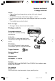
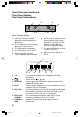
Quick Reference Front Panel Controls See the page number (in parenthesis) for full information about the item. Use Left-Right arrow keys to select a channel for display. Scanning stops. Push SCAN to resume. (22) Use Up-Down arrow keys to scroll thru the MENU. Otherwise inactive. (21) MENU Push to sequence through menu choices for instrument setup. (21) MENU °F EXIT Push to exit any menu or display mode. Operation continues.
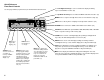
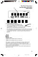
Quick Reference Continued Front Panel Display Rear Panel Connections 1 2 3 °F 2 4 ALARM STORE 5 4 6 7 8 Note: Example display 1. CH and the channel number display the thermocouple that is being read. 2. The number of the channel being displayed is repeated here. 3. The temperature is displayed. 4. The temperature scale is given. 5. A flashing channel number shows a problem with that probe. 6. Words across the bottom of the display indicate status of the instrument.
Rear Panel Connections Thermocouple connections Power switch A MODEL ####-## Mfg. By Barnant Company Barrington, IL 60010-2392 USA 12 CHANNEL TERMOCOUPLE SCANNER 1 2 7 8 3 4 9 10 PC/IN 5 6 11 12 OUT/LINK PARALLEL PRINTER 10-28 VDC 7-20 VAC 500 MA TRIGGER + GND RS232 B 1 2 3 4 5 6 7 8 9 10 11 12 A. Thermocouple connections • Connect up to twelve thermocouples here. • Jacks are for two blade mini-ANSI connectors. • Thermocouples of types B, E, J, K, N, R, S, or T can be used.
Rear Panel Connections continued 10-28V DC jack A B PC/IN jack MODEL ####-## Mfg. By Barnant Company Barrington, IL 60010-2392 USA 12 CHANNEL TERMOCOUPLE SCANNER 1 2 3 4 5 6 7 8 9 10 11 12 PC/IN OUT/LINK PARALLEL PRINTER TRIGGER + GND RS232 10-28 VDC 7-20 VAC 500 MA 10-28 VDC 7-20 VAC 500 MA A. 10-28V DC jack (Power supply input) Connect the input connector of the supplied AC adapter here. Polarity may be either center +, or center –, or AC.
Rear Panel Connections continued Out/Link jack Parallel Printer connection Trigger + Gnd connection MODEL ####-## Mfg. By Barnant Company Barrington, IL 60010-2392 USA 12 CHANNEL TERMOCOUPLE SCANNER 1 2 3 4 5 6 7 8 9 10 11 12 PC/IN OUT/LINK PARALLEL PRINTER 10-28 VDC 7-20 VAC 500 MA TRIGGER + GND RS232 A B C A. OUT/LINK jack Link connection. Connect OUT/LINK (using wire with RJ-11 connectors) to PC/IN connection on additional instruments.
Installation 1 MODEL ####-## Mfg. By Barnant Company Barrington, IL 60010-2392 USA 12 CHANNEL TERMOCOUPLE SCANNER 1 2 7 8 3 9 PC/IN 4 5 6 10 11 12 OUT/LINK PARALLEL PRINTER 8 2 TRIGGER + GND RS232 10-28 VDC 7-20 VAC 500 MA 5 6 4 1. Attach up to 12 thermocouples. 7 2 3 2. Connect the AC adapter to the instrument. 3. Plug the AC adapter into an outlet. 4 - 7 are Optional 4. Connect the PARALLEL PRINTER output to a PC printer (standard parallel port cable - not supplied). 5.
Front panel displays and controls 1 STORE button MENU . °F EXIT +ALARM 1 STORE 1 STORE 2 LOG 3 RECALL 4 PRINT 6 MIN 5 MAX 7 AVG 8 HOLD 9 SCAN 0 CLEAR 1 1 STORE button Push to store one record cycle of the current set of readings in memory. (Same as LOG, except only one record is stored.) When a numerical entry is required and the NUM icon is on, push to enter a ‘1’. a b °F STORE The word “STORE” a and the record number being stored b appear in the display for about 3 seconds.
Front panel displays and controls continued 2 LOG button MENU . °F EXIT +ALARM 1 STORE 2 LOG 3 RECALL 4 PRINT 5 MAX 6 MIN 7 AVG 8 HOLD 9 SCAN 0 CLEAR 2 2 LOG 2 LOG button Push to log record cycles as they are read. (Same as STORE, only continues automatically.) When a numerical entry is required and the NUM icon is on, push to enter a ‘2’. Push again to turn logging off. °F 4 LOG a The word “LOG” a appears and remains in the display while records are being logged.
Front panel displays and controls continued 3 RECALL button MENU . °F EXIT +ALARM 1 STORE 2 LOG 3 RECALL 4 PRINT 5 MAX 6 MIN 7 AVG 8 HOLD 9 SCAN 0 CLEAR 3 3 RECALL 3 RECALL button Push to recall stored (STORE or LOG) data. When a numerical entry is required and the NUM icon is on, push to enter a ‘3’. • “RECALL” appears and remains in the display during recall. • The LOG or STORE record number and time of channel 1 are displayed first.
Front panel displays and controls continued 3 RECALL button continued 4 PRINT button MENU . °F EXIT +ALARM 1 STORE 2 LOG 3 RECALL 4 PRINT 3 5 MAX 7 AVG 6 MIN 8 HOLD 9 SCAN 0 CLEAR 4 3 RECALL button continued • Any time during RECALL push the Up-Down arrow keys to scroll through the stored records. • Any time during RECALL push the Left-Right arrow keys to scroll through the channels. • To exit RECALL push EXIT.
Front panel displays and controls continued 5 MAX button MENU . °F EXIT +ALARM 1 STORE 2 LOG 3 RECALL 4 PRINT 5 MAX 6 MIN 7 AVG 8 HOLD 9 SCAN 0 CLEAR 5 5 MAX 5 MAX button Push to display the maximum temperature logged for each channel. The display continues to scan channels. When a numerical entry is required and the NUM icon is on, push to enter a ‘5’. °F 2 MAX • • • • • • “MAX” appears and remains in the display.
Front panel displays and controls continued 6 MIN button MENU . °F EXIT +ALARM 1 STORE 2 LOG 3 RECALL 4 PRINT 5 MAX 6 MIN 7 AVG 8 HOLD 9 SCAN 0 CLEAR 6 6 MIN 6 MIN button Push to display the minimum temperature logged for each channel. The display continues to scan channels. When a numerical entry is required and the NUM icon is on, push to enter a ‘6’. °F 2 MIN • • • • • • “MIN” appears and remains in the display.
Front panel displays and controls continued 7 AVG button 8 HOLD button MENU . °F EXIT +ALARM 1 STORE 2 LOG 3 RECALL 4 PRINT 7 AVG 5 MAX 6 MIN 7 7 AVG 8 HOLD 9 SCAN 0 CLEAR 8 7 AVG button Push to display the average temperature for each channel and the number of readings that are being averaged. The display continues to scan channels. When a numerical entry is required and the NUM icon is on, push to enter a ‘7’. °F 5 AVG • • • • • “AVG” appears and remains in the display.
Front panel displays and controls continued 9 SCAN button 0 CLEAR button MENU . °F EXIT +ALARM 1 STORE 2 LOG 3 RECALL 9 SCAN 4 PRINT 5 MAX 6 MIN 7 AVG 8 HOLD 9 SCAN 0 CLEAR 9 0 9 SCAN button Push to start a channel scan. When a numerical entry is required and the NUM icon is on, push to enter a ‘9’. • Each channel is displayed for three seconds. • Use to return to scanning after scanning is stopped by using the Left-Right arrow keys. • Causes an immediate scan.
Front panel displays and controls continued MENU button Up-Down Arrow keys MENU . °F EXIT +ALARM 1 STORE 2 LOG 3 RECALL 4 PRINT 5 MAX 6 MIN 7 AVG 8 HOLD 9 SCAN 0 CLEAR MENU Up-Down Arrow Keys MENU MENU button Push to scroll through the menu to enter or change setup parameters. The word “SCALE” appears in the display and the current scale setting (for example °F) flashes. To scroll backwards through the menu choices push and hold MENU then press the Left arrow key.
Front panel displays and controls continued Left-Right Arrow keys MENU . °F EXIT +ALARM 1 STORE 2 LOG 3 RECALL 4 PRINT 5 MAX 6 MIN 7 AVG 8 HOLD 9 SCAN 0 CLEAR Left-Right Arrow Keys Left-Right Arrow keys Active within the MENU. Used to scroll through menu options. • Manually select a channel.
Front panel displays and controls continued EXIT button ALARM button MENU . °F EXIT +ALARM 1 STORE 2 LOG 3 RECALL 4 PRINT 5 MAX 6 MIN 7 AVG 8 HOLD ALARM 9 SCAN 0 CLEAR EXIT EXIT EXIT button During MENU, push to EXIT the MENU and save any menu choices that have been made. SAVING SETUP is displayed for two seconds, then the instrument returns to scanning. During STORE, RECALL, MAX, MIN, AVG, CLEAR or HOLD displays, push to EXIT the display and return to scanning.
Front panel displays and controls continued ALARM button continued °F 2 4 STORE ALARM 3 Temperature Alarms continued • HI temperature alarm: When a thermocouple detects a temperature above the HI limit setting in the menu, ALARM is displayed, the alarm icon and the channel number 3 flash. HI will flash when that channel is displayed.
Front panel displays and controls continued ALARM button continued Other Alarms • OPEN thermocouple: A thermocouple channel that is OPEN (no thermocouple connected) will cause an OPEN alarm. OPEN will be displayed instead of a temperature when that channel is displayed. Check thermocouple connection, wiring to the thermocouple, or replace the thermocouple. If the channel is not used, disable the channel (see How to Enable/ Disable channels, page 30).
Front panel displays and controls continued 1 About the MENU MENU . °F EXIT +ALARM 1 STORE 2 LOG 3 RECALL 4 PRINT 5 MAX 6 MIN 7 AVG 8 HOLD 9 SCAN 0 CLEAR About the Menu Push the MENU button 1 to scroll through the menu to enter or change setup parameters. The word “SCALE” appears in the display and the current scale setting (for example °F) flashes. To scroll backwards through the menu choices push and hold MENU then press the Left arrow key.
Front panel displays and controls continued About the MENU continued About the Menu continued • Quick access - Push MENU then SCAN, PRINT, LOG, or ALARM to jump to that point in the menu. • When done with a menu setup either push EXIT to save the setup and return to scanning or push MENU to continue to the next menu setup. • If a numeric entry is required in a menu setup, a flashing NUM icon is displayed and the number and ± keys are active.
Front panel displays and controls continued How to set the scale °F How to set the scale The instrument can record, display and print at the following scales: °F Degrees Fahrenheit °C Degrees Centigrade °R Degrees Rankin K Kelvin The default scale is °F. 2 1b 1a 1, 3b 3a MENU °F EXIT +ALARM 1 STORE 2 LOG 3 RECALL 4 PRINT 5 MAX 6 MIN 7 AVG 8 HOLD 9 SCAN 0 CLEAR To set or change the scale: 1. Push MENU, SCALE 1a is displayed and the current scale setting 1b flashes. 2.
Front panel displays and controls continued How to change the resolution How to change the resolution The instrument can display and print temperatures at either 0.1° or 1° resolution. The default resolution is 0.1°. 1a 2 1b 1, 3b 3a MENU EXIT +ALARM 1 STORE 2 LOG 3 RECALL 4 PRINT 5 MAX 6 MIN 7 AVG 8 HOLD 9 SCAN 0 CLEAR To set or change the resolution: 1. Push MENU until RESOLUTION is displayed. RESOLUTION 1a is displayed and the current resolution setting 1b flashes. 2.
Front panel displays and controls continued How to Enable/Disable channels 1 2 3 4 5 6 7 8 9 10 11 12 How to Enable/Disable channels A thermocouple channel can be turned off if that channel is not used or not desired. A channel that is turned off will be skipped in a scan and listed as OFF in a printout. The default setting is all channels ON.
Front panel displays and controls continued How to setup thermocouple types 1 2 3 4 5 6 7 8 9 10 11 12 How to setup thermocouple types Thermocouples of types K, J, B, N, S, R, E or T can be used with this instrument. Any combination of thermocouple types can be used. See Appendix B for thermocouple specifications. The default setting for all channels is type K.
Front panel displays and controls continued How to adjust the display contrast How to adjust the display contrast The display contrast can be adjusted from 1 (very dark - the background interferes with the display) to 50 (very light - display letters and numbers are dim). This setting adjusts the contrast for varying viewing angles. The default setting is 25.
Front panel displays and controls continued How to set trigger type How to set trigger type A trigger (contact between pins 1 and 2 of the trigger) can be set to: • pulse print (print one record when trigger contact is closed). • S/S (start/stop) PRINT (equivalent to toggling PRINT on while trigger contact is closed). • pulse STORE (equivalent to pushing STORE to log one record). • S/S (start/stop) STORE (equivalent to pushing LOG to continuously log records while trigger contact is closed).
Front panel displays and controls continued How to set trigger mode How to set trigger mode If a trigger type is set to PRINT or STORE, the trigger mode can be set. (See How to set trigger type on preceding page.) The modes are PULSE (momentary action, as in pushing and releasing a button), and S/S (start/stop, toggle action as in switching on or off). The default setting is PULSE.
Front panel displays and controls continued How to adjust the scan rate NUM How to adjust the scan rate The scan rate is the interval between the start of individual scans of all twelve channels. The default setting is 00:04 (4 seconds). It takes 4 seconds to do one 12 channel scan, so a scan rate of 00:04 results in continuous scanning. With the scan rate at 00:20 there will be 3 scans per minute. The maximum scan rate that can be set is one hour (60:00).
Front panel displays and controls continued How to adjust the print rate PRINT NUM How to adjust the print rate The print rate is the time the instrument waits between printing temperature scans on the attached printer. A printer must be attached and turned on. The instrument only sends the data, there is no alarm or storage of print information if the printer is disconnected or turned off. The PRINT button must be pushed and PRINT displayed. The default setting is 00:20 (20 seconds).
Front panel displays and controls continued How to adjust the log rate LOG NUM How to adjust the log rate The log rate is the time the instrument waits between logging temperature scans in memory. 4,680 12 channel scans can be logged in memory, then LOG FULL is displayed. When LOG FULL is displayed you can RECALL – scroll through the logged readings, and you can PRINT – print the entire list of 4,680 logged entries. To clear (erase) memory: push CLEAR, then push LOG.
Front panel displays and controls continued How to adjust the log rate continued 1b 1a 1, 3b 3a MENU EXIT LOG NUM 1 STORE 1d +ALARM 2 LOG 3 RECALL 4 PRINT 5 MAX 6 MIN 7 AVG 8 HOLD 9 SCAN 0 CLEAR 2 1c To adjust the log rate continued: 1. Push MENU until the LOG RATE displays or push MENU at least once, then push LOG. RATE 1a is displayed and the current setting 1b flashes. LOG 1c is displayed. NUM 1d appears and flashes indicating number keys 2 are active. 2.
Front panel displays and controls continued How to set the alarm mode ALARM How to set the alarm mode The alarm mode can be ALARMS OFF, or ALARMS ON. The default setting is ALARMS OFF. In ALARMS OFF the instrument does not react to temperature extremes with an alarm. In ALARMS ON a HI or LO temperature alarm remains until manually reset. To set the alarm mode: 1b 1, 3b 2 3a MENU EXIT +ALARM ALARM 1 STORE 2 LOG 3 RECALL 4 PRINT 5 MAX 6 MIN 7 AVG 8 HOLD 9 SCAN 0 CLEAR 1a 1.
Front panel displays and controls continued How to set the alarm print ALARM How to set the alarm print Alarm print can be PRINT ON or PRINT OFF. The default setting is PRINT ON. When set to PRINT ON a record is printed on your attached printer when an alarm event occurs. 1b 1, 3b 2 3a MENU EXIT +ALARM ALARM 1 STORE 2 LOG 3 RECALL 4 PRINT 5 MAX 6 MIN 7 AVG 8 HOLD 9 SCAN 0 CLEAR 1a To set the alarm print: 1.
Front panel displays and controls continued How to set HI alarm(s) 1 2 3 4 5 6 7 8 9 10 11 12 ALARM HI OFF this setting is skipped in the MENU. The default settings are all 0’s (HI alarm off). To set HI alarm(s): 1c 1, 4b 3 2 4a MENU EXIT 1 2 3 4 5 6 7 8 9 10 11 12 ALARM 1 STORE 2 LOG 3 RECALL 4 PRINT 5 MAX 6 MIN 7 AVG +ALARM HI 8 HOLD 9 SCAN 0 CLEAR 1a 1b 1.
Front panel displays and controls continued How to set LO alarm(s) 1 2 3 4 5 6 7 8 9 10 11 12 ALARM LO How to set LO alarm(s) The alarm mode must be ALARMS ON. If the alarm mode is ALARMS OFF this setting is skipped in the MENU. The default settings are all 0’s (LO alarm off). 1c 2 1, 4b 3 4a MENU EXIT 1 2 3 4 5 6 7 8 9 10 11 12 +ALARM ALARM LO 1 STORE 2 LOG 3 RECALL 4 PRINT 5 MAX 6 MIN 7 AVG 8 HOLD 9 SCAN 0 CLEAR 1a 1b To set LO alarm(s): 1.
Front panel displays and controls continued How to set alarm hysteresis °F ALARM NUM How to set alarm hysteresis The alarm mode must be ALARMS ON. If the alarm mode is ALARMS OFF this setting is skipped in the MENU. Note: Defaults /settings are described in °F, the actual scale used is the scale that was previously selected. The default setting is 1.0°F. Hysteresis can be any value from 0.0°F to 99.9°F. Hysteresis is the ± temperature range before an alarm is out of range.
Front panel displays and controls continued How to adjust HI alarm setpoints °F 3 NUM ALARM HI How to adjust HI alarm setpoints The alarm mode must be ALARMS ON. If the alarm mode is ALARMS OFF this setting is skipped in the MENU. Only channels whose HI alarms are set to 1 (on) can have their setpoints changed. 1c 1a 1, 4b 2 4a MENU °F EXIT NUM 1 STORE 1f 3 2 LOG ALARM 3 RECALL 4 PRINT 1b 5 MAX 6 MIN 7 AVG +ALARM HI 8 HOLD 9 SCAN 0 CLEAR 3 1d 1e To adjust a HI alarm setpoint: 1.
Front panel displays and controls continued How to adjust LO alarm setpoints °F 5 ALARM LO NUM How to adjust LO alarm setpoints The alarm mode must be ALARMS ON. If the alarm mode is ALARMS OFF this setting is skipped in the MENU. Only channels whose LO alarms are set to 1 (on) can have their setpoints changed. 1c 1a 1, 4b 2 4a MENU °F EXIT 5 1 STORE 1f +ALARM ALARM LO NUM 2 LOG 3 RECALL 4 PRINT 1b 5 MAX 6 MIN 7 AVG 8 HOLD 9 SCAN 0 CLEAR 3 1d 1e To adjust a LO alarm setpoint: 1.
Front panel displays and controls continued How to Enable/Disable the alarm beeper How to Enable/Disable the alarm beeper Beeper on allows audible warning of alarm condition. Beeper off prevents audible warning. In either case, the icon will flash. This turns the audible beeper on or off. When off and an alarm occurs, icon is displayed. only the flashing alarm The following will cause an alarm: • Channel temperature higher than a HI alarm setpoint. • Channel temperature lower than a LO alarm setpoint.
Front panel displays and controls continued How to set the date format How to set the date format The date can be displayed MM/DD or DD/MM. 1b 1a 1, 3b 2 3a MENU EXIT +ALARM 1 STORE 2 LOG 3 RECALL 4 PRINT 5 MAX 6 MIN 7 AVG 8 HOLD 9 SCAN 0 CLEAR To set the date format: 1. Push MENU until the word DATE 1a is displayed and the current setting 1b flashes. 2. Push the Up or Down arrow keys to toggle between MM/DD and DD/MM. 3a. Push EXIT to save the setting and return to scanning, or 3b.
Front panel displays and controls continued How to set the date NUM How to set the date The date can be displayed MM/DD/YY or DD/MM/YY. Check the date format (previous page) before setting the date. The internal calendar is ‘smart’. It automatically adjusts for months with 28, 30 and 31 days, and even compensates for leap year. 1b 1a 1, 3b 3a MENU EXIT +ALARM NUM 1 STORE 2 LOG 3 RECALL 4 PRINT 1c 5 MAX 6 MIN 7 AVG 8 HOLD 9 SCAN 0 CLEAR 2 To set the date: 1.
Front panel displays and controls continued How to set the time NUM How to set the time The time must be set as 24-hour time. For times after 12:59 p.m. add 12 to the hours. Thus, 2:22 p.m. is 14:22, and 5:00 p.m. is 17:00. 1b 1a 1, 3b 3a MENU EXIT +ALARM NUM 1 STORE 2 LOG 3 RECALL 4 PRINT 1c 5 MAX 6 MIN 7 AVG 8 HOLD 9 SCAN 0 CLEAR 2 To set the time: 1. Push MENU until TIME 1a is displayed and the current setting 1b flashes. NUM 1c is flashing to indicate that number keys 2 are active.
Front panel displays and controls continued How to do a field calibration °F 5 NUM CAL How to do a field calibration Factory calibration is stored in protected, non-volatile memory. Field calibration is usually used to reduce probe errors over a specified range. All field calibration values may be cleared (returning the instrument to factory calibration) by pushing and holding CLEAR during the power up display test. An individual channel's field calibration may be cleared.
Front panel displays and controls continued How to do a field calibration continued 2a 2b 4 2, 5 MENU °F EXIT 5 NUM 1 STORE 2e +ALARM CAL 2 LOG 3 RECALL 4 PRINT 2d 5 MAX 6 MIN 7 AVG 8 HOLD 9 SCAN 0 CLEAR 2c 3 To do a field calibration continued: 1. Place the probe(s) at the desired temperature. 2. Push and release MENU until the display reads CALPT1, 2a. The entry point 2b flashes. CAL 2c is displayed. The channel number 2d is displayed.
Front panel displays and controls continued How to do a field calibration continued 9b 9a MENU EXIT PRINT 1 STORE 2 LOG 3 RECALL CAL 4 PRINT 5 MAX 8 +ALARM 6 MIN 7 AVG 8 HOLD 9 SCAN 0 CLEAR To do a field calibration continued: 8. Push Left or Right arrow keys to switch channels and enter their CALPT2, or if desired, 9a. Push EXIT to save the setting and return to scanning, or 9b. Push MENU to switch to the next setup topic (cal report).
Front panel displays and controls continued How to print a calibration report Note: This is only valid if an optional parallel printer is attached to the DB-25 (M) input connection. Alternately, this report may be obtained through “ScanLink”. 1b 2 1a, 3a 1c, 3b MENU EXIT PRINT 1 STORE 2 LOG 3 RECALL +ALARM CAL 4 PRINT 5 MAX 6 MIN 7 AVG 8 HOLD 9 SCAN 0 CLEAR To print a calibration report: 1. If MENU 1a is pushed the display REPORT NO with NO 1b flashing appears.
Front panel displays and controls continued How to print a calibration report continued To print a calibration report continued: Example field calibration report °F: Service calibration performed on 04/09/98 at 13:28:47 Field calibration status as of 04/09/98 14:12:41, scale Ch = F 1 2 3 CalPt.1 ------None 2.0 3.0 Change -----0.0 0.0 0.0 CalPt.2 ------None 900.2 900.3 Change -----0.0 0.1 0.7 Date -------04/09/98 04/09/98 04/09/98 Time -------14:01:45 13:58:51 13:58:51 4 5 6 4.0 5.0 6.0 0.2 0.1 0.
Front panel displays and controls continued How to calibrate to water How to calibrate to water Ice Point Calibrate CALPT1 to the freezing point of water (0°C or 32°F) by using crushed ice made of distilled water. Immerse the probe in a flask (insulated) filled with crushed ice and topped off with distilled water. Add crushed ice to keep the flask full of crushed ice and water during calibration.
Power up modes Power up modes are special ways to clear memory or defaults during power up. To activate a power up mode: MODEL ####-## Mfg. By Barnant Company Barrington, IL 60010-2392 USA 12 CHANNEL TERMOCOUPLE SCANNER 1 2 7 8 3 4 9 10 PC/IN 5 6 11 12 OUT/LINK PARALLEL PRINTER 2 TRIGGER + GND RS232 10-28 VDC 7-20 VAC 500 MA 1 1. Turn off the power using the power switch on the back of the instrument ( ). 2.
Power up modes continued Maintenance Care and cleaning Push and hold: MIN & MAX to restore factory MENU defaults, or Push and hold: MENU to display the firmware version. Push EXIT or CLEAR to switch to the scanning display. Care and Cleaning Clean the case by using a mild detergent. Avoid immersion and excess liquid.
Maintenance Battery Battery A lithium battery retains the date and time when power is off or the instrument is disconnected from its power source. At room temperature and with a new battery, memory will be retained for over a year. A BAD BATTERY error message is displayed if the battery voltage is low and the battery needs replacement. 3V LITHIUM + BR1225 Battery: Lithium button battery RAYOVAC® or PANASONIC® type BR1225, only.
WARRANTY Eutech Instruments supplies this product with a ONE-year warranty to be free from significant deviations from published specifications. If repair or adjustment is necessary within the warranty period, the problem will be corrected at no charge if it is not due to misuse or abuse on your part, as determined by Eutech Instruments. Repair costs outside the warranty period, or those resulting from product misuse or abuse, may be invoiced to you.
Specifications Operating Temperature (for stated accuracy) ........................ 18°C to 28°C (64°F to 82°F) Operating Temperature (useful range)................................... 0°C to 40°C (32°F to 104°F) Storage temperature ........................ –40°C to 60°C (–40°F to 110°F) Humidity (non-condensing) .................... 10 to 90% Altitude ................................................. Less than 2000 m Accuracy Thermocouple types E,J,K,N,T >–150°C ................................... ±(0.
Specifications continued Typical power usage ........................ 10–28V DC (non-polarized) Enclosure ............................................... molded ABS case UL-94V0 chemical resistance ......................... withstands standard cleaning solvents Pollution Degree .............................. Pollution Degree 2/ IEC664 (Indoor use—lab, office) ingress rating ................................... IP-32 per IEC 529 Printer connector .........................................
Appendix A Error messages Error messages are listed in alphabetical order, followed by a brief description of the error condition, followed by what action the user can take to correct the error (if possible). A/D TIMEOUT Return for service if error persists. BAD BATTERY Low battery voltage. Affects the clock and calendar. Replace the lithium battery inside the instrument. See pg. 58. BAD FLD CAL Bad field calibration checksum. All field calibration values are erased. Repeat field calibration if needed.
Appendix B Guidelines to Thermocouple Selection Type E Temperature range ................................. Environmental tolerance ........................ Color ...................................................... -250°C to 871°C oxidizing, inert atmospheres. violet, + lead violet, - lead red Type J Temperature range ................................. Environmental tolerance ........................ Color ......................................................
Appendix D Menu flow chart Push MENU to proceed to the next menu choice. Set scale °F Push EXIT to exit and save menu changes. Adjust resolution Push MENU & left arrow key to go backwards in the menu.
Appendix D continued Menu flow chart ENU & left arrow key ckwards in the m alarms on Push MENU to proceed to the next menu choice. alarms on Set alarm print ALARM Push MENU & left arrow key to go backwards in the menu.
Appendix E Factory Default settings A variety of parameters are user set-able using the MENU. Your menu settings are retained in memory even when the instrument is turned off or disconnected from a power source. When the unit is first turned on, the memory contains the factory default menu settings. To erase all the menu settings and reset the instrument to factory default menu settings: 1. Turn off the power using the power switch on the back of the instrument. 2.