Series G Model D METERING PUMP INSTALLATION, OPERATION, AND MAINTENANCE MANUAL sales@novatech-usa.com www.novatech-usa.
Precautions Amendment to Pump Manual For Pumps with PVC & 316SS Liquid Ends WHEN USED IN SWIMMING POOLS OR SPAS/HOT TUBS (ANSI/NSF 50) ! ! ! 1. Caution on Chemical Concentration: There is a potential for elevated chemical concentration during periods of no flow, for example, during backwash in the system. Steps, such as turning the pump off, should be taken during operation or installation to prevent this.
TABLE OF CONTENTS SECTION DESCRIPTION PAGE Series G Model D Pump Model Number and Options ................................................................................ iii 1.0 DESCRIPTION ............................................................................................................................................ 1 1.1 General Information ........................................................................................................................... 1 1.
SECTION DESCRIPTION PAGE 4.5 Corrective Maintenance ................................................................................................................... 16 4.5.1 Check Valve Assemblies Replacement: Liquid Ends SD2 and SD4 - PVC, PVDF, and H2SO4 ........................................................................................................................................ 16 4.5.2 Check Valve Replacement: Liquid End Sizes SD2 and SD4 - Polymer ............................. 17 4.5.
Frame and Liquid End (D Frame) Code Connections Liquid End Material Motor Stroking Speed Frame and Liquid End MACROY D PUMP MODEL NUMBER AND OPTIONS Liquid End Material Description Code Description SD2 Max 0.7 GPH / 175 PSI 2 PVDF SD4 Max 14.
THIS PAGE INTENTIONALLY BLANK iv
SECTION 1 DESCRIPTION 1.1 GENERAL INFORMATION The basic pump components as illustrated in Figure 1 are: The Series G Model D is a reciprocating, chemical dosing pump capable of producing flows up to 115 gallons per hour (430 liters per hour) at pressures up to 175 psi (12 Bar).
Figure 2: Stroke Control Operating Principle 1 2 (A) (B) 3 4 Zero Stroke Setting 5 (B) (A) 7 (A) Suction Phase 6 Worm Worm Gear Eccentric Connecting Rod Discharge Phase 8 Setting to Maxmum Stroke 1 2 3 4 (B) Diaphragm Stroke: two times the distance between (A) and (B) Position at rear neutral point Position at forward neutral point 5 6 7 8 1.
As the diaphragm starts forward on the discharge stroke the pressure immediately rises inside the liquid end. When the liquid end pressure rises above the discharge line pressure, the discharge ball check is “pushed” upward and the process fluid in the liquid end flows into the discharge line. When the discharge stroke ends, the diaphragm momentarily stops again. The pressure in the liquid end equalizes with the discharge line pressure and the discharge ball check reseats. The cycle then starts again.
THIS PAGE INTENTIONALLY BLANK 4
SECTION 2 INSTALLATION 2.1 UNPACKING Electrical Equipment Pumps are shipped f.o.b. factory or representative warehouse and the title passes to the customer when the carrier signs for receipt of the pump. In the event that damages occur during shipment, it is the responsibility of the customer to notify the carrier immediately and to file a damage claim. Carefully examine the shipping crate upon receipt from the carrier to be sure there is no obvious damage to the contents.
Figure 3: Series G Model D Dimensional Outline 2.5 DRIP COLLECTION ING PLACE. A NOTICE SHOULD BE POSTED BY THE POWER SWITCH TO WARN THAT SERVICING IS BEING CARRIED OUT ON THE EQUIPMENT. SWITCH OFF THE POWER SUPPLY AS SOON AS ANY FAULT IS DETECTED DURING OPERATION (EXAMPLES: ABNORMALLY HIGH DRIVE TEMPERATURE, UNUSUAL NOISE, DIAPHRAGM FAILURE). In the event of a failure of the diaphragm or oil seal bellows, provisions need to be made to contain the process fluid or pump oil.
Figure 4: Typical Installation 4 6 3 5 4 6 1 5 1 3 2 4 6 9 1 3 5 8 7 1 2 3 4 5 6 7 8 9 - Tank Foot Valve (with Filter) Metering Pump Process Piping Bleed Valve 7 Injection Nozzle Shut-off Valve Filter Pulsation Damper -
Figure 5: General Piping 2.6.1 NPSH CONSIDERATIONS Because vapor in the liquid end will cause inaccurate pump delivery, piping should be sloped up from pump suction check to the supply tank to prevent formation of vapor pockets. Size piping to accommodate peak instantaneous flow. Because of the reciprocating motion of the pump diaphragm, peak instantaneous flow is approximately equal to 5 times the average flow. For example, a pump rated for 16 gallons per hour (61 L/hr.
2.7 VALVES tive pressure applications it is important that all connections be absolutely drip free and vacuum tight, and that a foot valve be installed at the bottom of the suction line (see upper left illustration of Figure 4). Back Pressure Valves All metering pumps are prone to overpumping (excessive output) at low discharge pressures. To prevent this condition from occurring, it is necessary to maintain approximately 10 psi (0.7 bar) back pressure against the pump.
2.8 ELECTRICAL CONNECTIONS OPERATION WITH THE WRONG MOTOR ROTATION MAY DAMAGE THE PUMP AND MOTOR AND VOID THE WARRANTY. DO NOT FORGET TO CONNECT THE EARTH TERMINAL ON THE MOTOR TO THE EQUIPMENT EARTH CONDUCTOR. Ensure that the electrical supply matches the pump motor nameplate characteristics. Connect the motor in accordance with the instructions and connection diagrams on the motor (or in the motor terminal box).
SECTION 3 OPERATION 3.1 START-UP PROCEDURES AND CHECKS flowing from the priming valve. If no priming valve is in place, when the liquid end is primed, the discharge check valves can be heard to be operating (should hear a clicking noise caused by movement of check valve balls). When liquid end is primed, stop the pump and close the priming valve. Check that the pump is secured to its support.
ITEM NO. NOMENCLATURE ITEM NO. NOMENCLATURE ITEM NO. NOMENCLATURE ITEM NO.
SECTION 4 MAINTENANCE 4.1 PREVENTATIVE MAINTENANCE Initially, change the oil in the pump drive assembly after the first 1000 hours of operation. Thereafter, change drive oil on an annual basis or after every 5000 hours of operation. packed in the shipping crate with any pump shipped for repair. These safety precautions will aid the troubleshooting and repair procedure and preclude serious injury to repair personnel from hazardous residue in pump liquid end.
Figure 7: Diaphragm Assemblies By Liquid End Size and Material 260 274 260 252 271 240 250 270 SD2 SD4 (Plastic) 260 260 274 274 271 240 271 251 240 250 250 270 253 270 SD7 and SD8 SD4 (316SS) 4.4 SPARE PARTS 4.4.1 SIZE D2 LIQUID ENDS - PVC, PVDF, POLYMER, AND H2SO4. The following spare parts should be stocked for each pump to prevent serious delays in repairs. (Refer to Figures 7 thru 14).
1 each, PTFE Washer: Item 274 in Figure 12. 2 each, O-Ring: Item 419, Seat: Item 420, Ball: Item 422, Cartridge: Item 426, Washer: Item 427 and Spring: Item 428 (Discharge Only) in Figure 9. 2 each, Cartridge Assy.: (P/N 39461) Included in Kit and Coupling Nut: Item 428 in Figure 12. Liquid End Kit for D2 H2SO4 Liquid End Kit for D4 Slurry Includes: RPM 212, Includes: 1 each, Diaphragm: Item 260 in Figure 9. 1 each, Diaphragm: Item 260 in Figure 12. 1 each, Oil Seal Bellows: Item 70 in Figure 9.
Check Valve Replacement 2 each, Seat: Item 420, Ball: Item 422 in Figure 13. General 4 each, O-Ring: Item 419 in Figure 13. Before beginning work on the valve assemblies, make sure the suction and discharge shut-off valves are closed and that pressure has been bled from the pump liquid end. When replacing the valves, be sure to replace the valve O-rings. Pay close attention to the proper assembly and orientation of the check valves as shown in each Liquid End figure.
Suction 1. Unscrew the valve body (424) from the pump head (280). 2. Remove the valve assembly: assembly includes ball (422), seat (420), Cartridge (426), O-ring (419), and washer (427). DO NOT APPLY PTFE TAPE TO THE THREADS OF CHECK VALVE BODY THAT SCREWS INTO THE HEAD (280), AS THIS MAY PREVENT ADEQUATE SQUEEZE FROM BEING APPLIED TO THE VALVE O-RING WHICH COULD RESULT IN LEAKAGE. 3. Clean the valve body (424) and threaded port in the head (280). 4. Place a new washer (427) into valve body (424).
Disassembly 2. Unscrew the check valve assembly (425) from the pump head (280). Remove the check valves by unscrewing them from the pump head. 3. Screw the union nut part way (one or two turns) onto the end of the ball guide (424) that has the seat in it. Be sure the union nut is on loosely. This will allow a gap for the seat (420) to fall into as it is removed from the ball guide.
(C) REVERSE PUMPING ACTION (FROM DISCHARGE LINE INTO SUCTION LINE) 2. Remove the valve assembly: assembly includes two O-rings (419), seat (420), ball (422), poppet (426), spring (423) and check valve body (424). 1. Drop the ball (422) into the curved inner chamber end of the body (424). 3. Replace O-rings (419), seat (420), ball (422), poppet (426), and spring (423). 2. Set the body on a flat surface so that the end with the ball faces upward.
4.6.1 DIAPHRAGM REPLACEMENT: LIQUID END SIZE SD2 (SEE FIGURES 6, 9, AND 10) Reassembly 1. Loosen the head screws (Item 290 in Figure 9) and remove the diaphragm head (Item 280 in Figure 9). Mark the suction and discharge ports on the diaphragm head prior to removal. THE ORDER OF ASSEMBLY AND ORIENTATION OF THE SUCTION AND DISCHARGE CHECK VALVES IS DIFFERENT. REFER TO FIGURE 14 FOR PROPER ASSEMBLY ORDER AND ORIENTATION.
5. Make sure that stainless steel support nut (270) is clean and free of corrosion. When cleaning the support nut, take care not to scratch the smooth angled surface of the support nut. If corrosion cannot be removed without damaging the support nut, replace with a new one. Note: Steps 13 and 14 are applicable to Liquid End Size SD7 and SD8 (See Figure 6). 15. With the capacity still set at 100% turn the motor fan until the diaphragm is pulled back to the rearward position (bottom dead center). 6.
4.8 RESTARTING THE PUMP 7. Remove the diaphragm support ring (Item 230 in Figure 12) from the spacer (225). 1. Reconnect the pump to the piping system. 8. Drain the oil out of the pump drive by removing the drain plug from the pump housing (Item 20 in Figure 8). 2. Check that capacity is set to 0%. 9. Remove oil seal bellows clamping components as follows: 3. Open system suction and discharge shut-off valves and restart pump.
SECTION 5 PARTS LIST GENERAL 1. This section gives information regarding replaceable components. ILLUSTRATED PARTS LIST 1. Figure and Item Number Column (a) The item numbers shown in the detailed parts list correspond to the item numbers appearing on the exploded view illustration. To find an unknown part number, locate the part on the illustration and note the item number. Look for the item number on the detailed parts list. The part number is on the same line.
Figure 8.
5.
Figure 9: D2 Plastic Liquid End 26
5.2 PARTS LIST FOR D2 PLASTIC LIQUID END PVC, PVDF, H2SO4, AND POLYMER-NPT / PVC, PVDF TUBING.
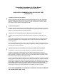
Figure 10: SD2 Metallic Liquid End 227 252 ASSEMBLY 425 230 290 260 280 ASSEMBLY 225 70 425 210 5.
Figure 11: SD4 Metallic Liquid End 230 227 225 ASSEMBLY 425 271 280 290 240 251 250 253 ASSEMBLY 425 270 210 274 260 5.4 PARTS LIST FOR SD4 METALLIC LIQUID END STAINLESS STEEL-NPT Model: SD4 _ _ 7P FIGURE NUMBER ITEM NUMBER 11 210 225 227 230 240 250 251 253 260 270 271 274 280 - Items not shown.
5.4 PARTS LIST FOR D4 METALLIC LIQUID END STAINLESS STEEL-NPT Model: D4 _ _ 7P _ _ _ _ A (316SS) FIGURE NUMBER ITEM NUMBER 11 290 425 - PART NUMBER DESCRIPTION 61059 CV202294 RPM 104 Pan Head Screw, #10-24 X 3/4 Check Valve Assembly Liquid End Kit, 316SS - Items not shown.
5.5 PARTS LIST FOR D4 PLASTIC LIQUID END PVC, PVDF, H2SO4, SLURRY, AND POLYMER-NPT / PVC, PVDF, AND , H2SO4-TUBING.
5.5 PARTS LIST FOR D4 PLASTIC LIQUID END PVC, PVDF, H2SO4, SLURRY, AND POLYMER-NPT / PVC, PVDF, AND , H2SO4-TUBING.
THIS PAGE INTENTIONALLY BLANK 33 44
Figure 13: D7 & D8 Plastic Liquid End 34
5.6 PARTS LIST FOR D7 AND D8 PLASTIC LIQUID END PVC-NPT/TUBING, PVDF-NPT, POLYMER-NPT, SLURRY-NPT, & H2SO4-NPT. Model: Reference Code: Model: D7/D8_ _ 8P _ _ _ _ A (PVC NPT) D7/D8_ _ NP _ _ _ _ D (H2SO4 NPT) D7/D8_ _ 2P _ _ _ _ B (PVDF NPT) D7/D8_ _ PP _ _ _ _ E (POLYMER NPT) D7/D8_ _ LP _ _ _ _ C (SLURRY NPT) D7/D8_ _ 8T _ _ _ _ F (PVC TUBE) D7/D8_ _ NP _ _ _ _ D (H2SO4 NPT) FIG. NO. ITEM NO.
5.6 PARTS LIST FOR D7 AND D8 PLASTIC LIQUID END PVC-NPT/TUBING, PVDF-NPT, POLYMER-NPT, SLURRY-NPT, & H2SO4-NPT. Model: Reference Code: Model: D7/D8_ _ 8P _ _ _ _ A (PVC NPT) D7/D8_ _ NP _ _ _ _ D (H2SO4 NPT) D7/D8_ _ 2P _ _ _ _ B (PVDF NPT) D7/D8_ _ PP _ _ _ _ E (POLYMER NPT) D7/D8_ _ LP _ _ _ _ C (SLURRY NPT) D7/D8_ _ 8T _ _ _ _ F (PVC TUBE) D7/D8_ _ NP _ _ _ _ D (H2SO4 NPT) FIG. NO. ITEM NO.
Figure 14: D7 & D8 316SS Liquid End 37
5.7 PARTS LIST FOR SD7 AND SD8 316SS-NPT LIQUID END Model: SD6 _ _ 7P or SD8 _ _ 7P FIG. NO. ITEM NO. DESCRIPTION SD7 PART NO.
SECTION 6 TROUBLESHOOTING SYMPTOMS 1. Pump motor won't operate. 2. Insufficient pump delivery. POSSIBLE CAUSE REMEDY a) Low process liquid level in the tank. a) Add liquid. b) Worn or dirty check valves. b) Clean or replace. c) Blocked discharge line. c) Clear line. d) Frozen liquid. d) Thaw liquid throughout pumping system. e) Blown fuse. e) Replace fuse. f) Open thermal overload device in motor starter. f) Reset device. g) Broken wire. g) Locate and repair. h) Low voltage.
SYMPTOMS 3. Erratic pump delivery. 4. Motor and pump body hot. 5. Pump still pumps even at zero capacity setting. 6. Gear noise. 7. Loud knock with each stroke. 8. Noisy operation in liquid end. POSSIBLE CAUSE REMEDY a) Leaky suction piping. a) Repair piping. b) Leaky safety valve. b) Repair or replace valve. c) Insufficient suction head. c) Raise suction tank level and/or install foot valve in suction line. d) Liquid near boiling. d) Cool liquid or increase suction head.
THIS PAGE INTENTIONALLY BLANK 41
201 Ivyland Road • Ivyland, PA 18974 USA • (215) 293-0401 • Fax: (215) 293-0445• www.lmipumps.com E-mail: info@lmipumps.