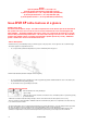
DVR XP TM (Xtra Performance) WOODLATHE Publication 115-0513-003 115-0513-003 1 INSTRUCTION MANUAL NOVA
Models 1)55175 spindle thread 1 1/4" x 8 tpi 115v 2) 55180 spindle thread M33x3.5 220-240v (Europe) 3) 55177 spindle thread 1 1/4" x 8 tpi 220-240v (Australasia) 4) 55178 spindle thread 1 1/4" x 8 tpi 220-240v (UK) 5) 55181 spindle thread 1 1/4" x 8 tpi 220-240v (South Africa) Nova DVR XP Lathe Features at a glance DVR Electronic drive The Nova DVR XP lathe is unique. The DVR incorporates the motor built as part of the headstock, the spindle and motor are one unit.
Solid Construction Bed Extension Segment Main Bed Segment Well proven design, the Nova DVR XP is made from Cast Iron components for strength and rigidity. Added features like the heavy duty TRIMAX triple bearing system and special webbed bed design makes the lathe well equipped to take heavy turning stresses. The bed has been designed with vibration dampening qualities - a solid 1/2" cross rib is positioned along the bed unit, quickly dissipating any vibration as it travels down the bed.
Welcome Thank you for choosing our Nova DVR XP Woodlathe and welcome to the NOVA product family. Your choice shows you want the best for your woodturning and you recognise the superb DVR drive technology and the host of other unique features the Nova DVR XP offers. We strive to achieve the best value for your money – providing quality, innovative features, a wide range of accessories – plus comprehensive, ongoing support (latest manuals downloadable from our website, newsletters, projects etc).
Contact NOVA New Zealand and Rest of the World Teknatool International Ltd Phone: (+64) 9 477 5600 Email: service@teknatool.com Website: www.teknatool.com United States NOVA Innovation and Customer Care Center Phone: 727-346-4775 Email: service@teknatool.com Website: www.teknatool.com Or you can contact the retailer where you purchased your NOVA DVR XP Wood lathe, for the contact details please see our website www.teknatool.
Table of Contents GENERAL SAFETY RULES ...................................................................................................................... 7 ADDITIONAL SAFETY RULES FOR WOODLATHES .............................................................................. 8 DVR XP Woodlathe Specifications ............................................................................................................ 9 Workshop Requirements ...................................................................
The information and specifications contained herein are subject to change. Teknatool is not responsible for errors or omissions herein or for incidental damages in connection with the furnishing or use of this information. GENERAL SAFETY RULES ! 1. 2. Warning! Failure to follow these rules may result in serious personal injury. FOR YOUR OWN SAFETY, READ THE MANUAL BEFORE OPERATING THE TOOL. Learn the machine’s application and limitations plus the specific hazards particular to it.
ADDITIONAL SAFETY RULES FOR WOODLATHES ! Warning! Failure to follow these rules may result in serious personal injury. Important: ALWAYS BEFORE SWITCHING SPINDLE ON, CHECK SCREEN FOR CORRECT SETTING 1. DO NOT MODIFY OR USE LATHE FOR USES OTHER THAN FOR WHICH IT WAS DESIGNED. 2. SEEK INSTRUCTION. If you are not thoroughly familiar with the operation of woodlathes, obtain advice from your supervisor, instructor, or other qualified person. Instruction from a qualified person is strongly recommended. 3.
DVR XP Woodlathe Specifications Size: 1100mm(L) x 240mm (W) x 412mm(H) 43 1/3"(L) x 9 1/2" (W) x 16 1/4"(H) Weight: 82kg (181 LB) Swing Over Bed: 400mm (16in.) Distance Between Centers: 600mm (24in.); extendable in 510mm (20in.) units with add-on Bed sections. Swing Outboard: 740mm (29in.) with headstock at 90° using outrigger toolrest. Headstock: (1) Spindle Thread: M33 x 3.5 RH or (2) 1-1/4 x 8 TPI RH Headstock Bore: No. 2 Morse Taper (#2 MT) Headstock Swivel: 0 to 360 degrees, with detents at 0, 22.
Setting Up Your Workshop Workshop Requirements Consideration Recommendation Lathe location Locate the Nova DVR XP close to a power source in an area with good lighting. Leave enough clearance on all sides of the lathe; allow for motor clearance when the headstock is swiveled. Other machines in your shop should not interfere with the operation of the lathe. Lighting Your shop should have adequate lighting. The work area of the lathe should be well lit; there should not be shadows cast on your work.
Example of Shop-made Lathe Stand This has been designed with economy of space in mind. Heavier sections, wider rails and gussets on the corners are encouraged. For stability and vibration dampening, it is highly recommended that the base is filled with sand. Top 43 x 16 x 2 in. Upper Leg Brace (2) 1-1/2 x 3-1/2 x 13 in. Machine Bolt (12) Upper Rail (2) 1-1/2 x 3-1/2 x 33 in. plywood bottom (compartment for sand) Lower Rail (2) 1-1/2 x 7-1/2 x 33 in.
Assembling the Nova DVR XP 1. Unpack the lathe and components from the shipping container. This is best done by cutting down the sides of the box to expose the lathe ! 2. Warning! Have other people help when moving or lifting the Nova DVR XP Woodlathe; it weighs about 82kg (181 LB). Clean any parts coated with rust preventative with a cloth moistened with a petroleum-based solvent or cleanser, such as paint thinner. Coat the lathe bed with paste wax.
Installing the Headstock Lockpin 3. Remove the plastic shipping tube from headstock base. Immediately screw the Headstock Lockpin into the threaded hole at the bottom of the headstock. Insert the operating bar into the hole in the Lockpin and firmly tighten the Lockpin to lock the headstock in position; then remove the operating bar. NOTE: When the pin is fully engaged the groove machined into the pin furthest from the thread should line up with the edge of the hole in the casting.
with the wrench from the bottom of the bed. ! Warning! Do not use a metal hammer to pound on the extension bed. This may damage the bed, affect accuracy and tailstock action, and may prevent you from adding another extension bed. 4. Bring the Tailstock along until it is on top of the join area where the bed extension face meets the lathe bed face. The bed extension may need to be manipulated up-and-down and sideways in order for the Tailstock to fit. 5.
Mounting the Lathe to a Support Surface Maximum of 25mm (1in.) (Required only for mounting the Outrigger Unit option Mounting Holes(6) (M12 x 1.75 Bolts) ! Optional Mounting Underneath lathe The lathe must be fastened to a support surface, such as a lathe stand or bench 2 x (M10 x 1.5) 1. Place the lathe on the stand top. Locate the front and left corner of the lathe approximately 25mm (1in.) from the corner edge of the stand top.
Using the Nova DVR XP Parts of the Nova DVR XP Woodlathe DVR Variable Speed Controller The Nova DVR XP drive is a unique type of motor and controller where the motor and controller interact. The motor provides data to the controller on its position and load conditions. The motor provides high torque even at low rpm and inherits extremely close speed control. With the toggle switch in the Off position, plug lead into wall socket and switch on.
DVR Drive Functions 1 3 2 4 6 8 5 7 A two-string liquid-crystal display panel (LCD) displays the current information. Ready to start at XXXXrpm >> “XXXX” is the reference motor speed. “>>” Indicates forward direction of rotation. 1. Green ON -- Press to start machine at the commanded speed -- always check that the speed has been selected correctly. When the computer is first switched on it is set at a default speed of 500 rpm.
The Direction of rotation setting is only available in the ready to start mode. Press stop if necessary, and press FWD/REV to toggle direction of rotation. The two arrows on the left side indicate reverse. Whenever reverse is selected a “ Warning Reverse Selected “ will flash on screen for about 1-2 seconds before spindle starts. Special and Parameter settings ! You may wish to change the stabilization setting from time to time depending on the type of work piece you are working on.
Turning Tips The Nova DVR XP drive technology is not just a variable speed motor -its smart motor technology takes turning to a new level. The speed, vibration, and load sensing, work with the conditions and turning. The machine will reward skilled turning with exceptional finish conditions. There is often no need for sanding. As you apply load (chisel pressure or depth of cut) the control will sense the change in spindle conditions and compensate accordingly.
Swiveling the Headstock 1. Stop the lathe. Insert the operating bar into a hole in the Headstock Lockpin. Loosen the Lockpin half a turn. 2. Slide the Headstock Release Handle towards outboard end of lathe, and rotate the headstock to a detent position. Do not push down on the handle. ! Warning! Use the detent latch positions to prevent headstock movement during turning. 337.5° 180° 4. Firmly tighten the Headstock Lockpin with the operating bar; but do not use excessive force. Remove the operating bar.
Headstock The headstock houses the Rotor, Stator, Electronics, bearings, and the Spindle. The headstock spindle accepts centers and accessories with no. 2 Morse taper (#2 MT), plus threaded faceplates and chucks. Spindle Thread Size Country Threads United States, Canada, Australia, New Zealand, South Africa, United Kingdom. 1-1/4 x 8 TPI RH Europe (excluding the UK) M33 x 3.5 RH Mounting a faceplate or chuck 1. Use the Spindle Index Pin to lock the headstock spindle. 2.
Using a spur center Mount the spur center to the work piece as shown and then insert the spur center and work piece into the headstock spindle. ! Warning! Do not pound work piece into headstock drive center when turning between centers or you may damage the headstock. To remove the center, insert a 10mm (3/8-inch) diameter wooden dowel or steel rod through the headstock spindle hole. While holding the center so it doesn’t fall, tap it out.
Lathe Turning speeds Correct selection of turning speeds is important for safety and finish cut quality It is important to take into account the fixing of the work piece, it should be made as secure as possible. Various techniques are available for this consult books on the subject and seek training opportunities. There are safety and out of balance considerations. Aim for a good balance in turning speed, ensure good fixing and try to balance timber as much as possible before installing on lathe.
Learning Turning The art and technique of turning is a subject beyond the scope of this instruction manual. It is recommended that you receive hands-on instruction on lathe turning and/or refer to books and videos on the subject.
CONTROLLER USER’S GUIDE NOVA DVR (SWITCHED RELUCTANCE) DRIVE Control Software versions 4.54x Interface Software version s03 Teknatool International 13th July 2006 1.0 1.1 INTRODUCTION General This guide contains the basic information on use of the Digital Variable Reluctance (DVR) electrical drive for DVR 3000/XP lathe. 1.2 Overview The DVR integrated electrical drive system contains the DVR motor with the Rotor Position Sensor (RPS), the drive control board and the human-machine interface (HMI).
3.0 HUMAN MACHINE INTERFACE DESCRIPTION The Human Machine Interface (HMI) provides a flexible choice of the drive parameters: run/stop, motor speed, direction of rotation, PI speed controller coefficients. HMI contains 2-lines, 16-position LCD display and keyboard. The drive parameters can be set by decreasing/increasing values incrementally. Some parameter values can be stored in the EEPROM of HMI.
4.0 CONTROL FUNCTIONS Drive Parameter Settings (Set Function) HMI display lines contain the parameters, which can be edited. Press key UP RPM DOWN RPM to incrementally increase the parameter or to decrease it. Hard Reset Function 0 OFF DOWN RPM Press key , hold it and then press key in order to provide the Hard Reset of the drive. Another way is to switch off the power, wait 10 seconds and switch it on again.
5.0 5.1 CONTROL OPERATIONS AT STOP MODE Starting operation Insert the drive power plug into the 220-230/115v, 50/60 Hz socket. There must be the sound signal and display messages step-by-step will be: (shown on the next page) TEKNATOOL Int. v4.54xs03 2006 TEKNATOOL PROMOTES SAFETY FIRST ALWAYS WEAR FACE SHIELD ENSURE CORRECT SPEED SELECTED Beeper will sound twice. Wait for end it or press key be: 0 OFF to cancel. After that the display message will TEKNATOOL Int. v4.
5.2 Reference speed setting. Preset (favorite) speed selection and set function There are 5 preset speeds available in the drive. The factory-preloaded reference speeds are: Number #1 #2D #3 #4 #5 Speed (rpm) 250 500 750 1020 1250 Note: The speed #2 is default speed number. The letter D after the number #2 indicates it is default. MODE M Press the key , hold it and press number to the next one.
Pick a preset number you would like to change. IMPORTANT Note: The default speed (#2D) can not be set at more than 500 rpm and the saved preset speed values will work also after Hard Reset Function. • SELECTOR E in order to make the request for saving the new value of pre-selected speed in Press the key the EEPROM (memory). It will display the symbol ‘?’ at the end of LCD line. Change the speed you require. • PROGRAM P Press key to store the new value.
5.4 The Speed Control Loop. The PI Speed Control coefficients setting The control system of the DVR Drive has Speed Control Loop which provides the PI speed controller function. The KPror and KInt are the values of the Proportional and Integral coefficient of speed control loop. They are functions of motor speed. See Appendix A for the basic curves of the PI speed controller coefficients. There are three possible choices – Normal (default), Soft and Hard coefficient curves.
5.5 Serial Number view. PROGRAM P • Press (“Page”) again to see Board Serial Number: LCD View SERIAL NUMBER 04067648 Comments The Control Board Serial Number MODE M Press (“Main”) to go to Main display page from any other display pages.
Maintaining the Nova DVR3000 General Maintenance Always isolate from power supply (unplug) before carrying out any maintenance Interval Maintenance After each use Clean the work area and Lathe. Vacuum shavings and dust from the Headstock, Tailstock, under the Toolslide and in between the bed. Monthly Wax exposed cast iron parts with a good quality paste wax, especially the bed rails. Buff out the wax thoroughly. Check tightness of nuts and bolts.
Cleaning the Toolslide If the toolslide becomes hard to move and adjust, cleaning and lubricating are required. 1. To make the toolslide slide more freely along the bed, make sure the bed rails are clean. Apply some paste wax to the rails. 2. If the toolslide is hard to move towards or away from you, remove the toolslide from the lathe bed. Clean the toolslide camshaft (round eccentric rod) with a petroleum-based solvent. Lubricate the rod with lightweight oil or a silicone spray. 3.
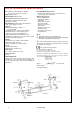
Aligning the Tailstock 1. Crank the Handwheel back so the quill is all the way in. 2. Place any #2 MT accessories you have that have a sharp point like a spur center, or live center in the tailstock quill and another center in the headstock spindle. Note: Tailstock alignment can be made easier by using the Teknatool Acruline Accessory Center in place of the centers. 3. Move the tailstock close to the headstock so the two centers nearly touch; check the alignment of the center points.
Voltage selection By removing a small jumper the unit will efficiently run on 220V and a gain in power can be achieved. Or the jumper can be replaced to enable the unit to run on 115V. 1. Ensure that the power is off and that the plug is disconnected from the wall. 2. Allow minimum of 3 minutes discharging time for capacitors before opening rear panel. 3. Remove the rear lower switch panel. This will expose the main control panel in the lower compartment. 4.
5. Carefully place your index finger on the edge of the board avoiding any soldier points. Using the top of your finger as a guide run the pliers along and lightly grab the jumper in the pliers. Do not squeeze too tight as you may crush the jumper. This is important as the jumper will need to be placed back should you want to run 115V again. 6. Reattach rear guard ensuring all wiring is captured inside casting.
Troubleshooting Guide Problem Excessive vibration. Possible Cause and Solution Out of balance, or large work piece. Reduce lathe speed to the lowest speed possible and turn the work piece to a true circle. Adjusting the speed using the up / down keys will change the speed in 10 rpm increments. If you try adjusting the speed up or down you will find that it is easy to find speed points that will minimize vibration and is one of the biggest advantages of DVR technology. Work piece is not held in the center.
Display screen shows Rotor Fault RP State Error LCD screen shows PFC Corrector Press off button; switch off computer by master switch wait one minute and switch on again. Check that the spindle index is not engaged or that something is preventing the spindle from turning. Note leaving the spindle index unit in will not harm the motor, however it will put some strain on the index unit.
Troubleshooting Guide continued Problem Possible Cause and Solution Tailstock and headstock center not lining up correctly. Bed incorrectly bolted to stand causing twist. Ensure stand and lathe are correctly installed. Headstock not returned to detent position after it has been rotated. Ensure that the headstock is locked into a detent position. Headstock Lockpin not fully seated. Twist the headstock back and forth to make sure it is properly seated and then tighten the Lockpin.
DVR XP Woodlathe Parts List Item # Qty Part # 1 2 3 4 5 6 7 8 9 10 11 12 13 14 15 16 17 18 19 20 21 22 23 24 25 26 27 28 29 30 31 32 33 34 35 36 37 38 39 40 41 42 43 44 45 46 47 48 49 1 1 1 1 1 1 4 4 4 1 1 1 1 1 1 1 1 1 1 1 1 1 1 1 1 2 4 4 1 1 1 2 1 1 1 1 1 1 1 1 1 1 1 1 1 1 1 1 2 55048 24118 24023 24060 55176 NHZ8 SW12 FW12 24011 24119 55029 FW12 55037 55026 24040 25028 G0610 55028 55153 TP0820 24065 24043 55027 55025 24048 25029 FW8 BHC0816 27002 K1225 24120 865913 25001 24026 55153 24020 G0610 K1225
Item # Qty Part # 50 51 52 53 54 55 56 57 58 59 1 1 4 1 1 1 1 1 4 1 1 1 1 1 1 1 1 1 1 1 1 1 1 1 1 1 1 8 1 1 1 1 1 1 55012 55145 M5 55040 55019 55014 55010 55049 M3 CSK Screw 55003 55103 55007 55005 55050 55009 55146 55004 55006 6207RS1-C0 EC35 55051 G0606 55011 55174 55100-55130 55018 55212 MP05010 55124 LHB 55152 55061 55172 55081 60 61 62 63 64 65 66 67 68 69 70 71 72 73 74 75 76 77 78 79 80 81 82 Description Swivel Pin-Headstock Headstock M5x10 screw Backing Plate Interface Board Front Control Cov
115-0701-001 - 43 -
Accessories Add On Bed Extension: 55195 Extend the bed of your Nova DVR XP Woodlathe for greater capacity for turning between centers. Each bed unit adds 510mm (20in.) Lathe Stand The stand pieces are cast from a high grade of Cast iron with extremely good section thickness and CAD generated internal gussets at all critical points to withstand extremely high stresses with practically no distortion.
Accessories Faceplates: SFP80L (with side-locking function). Faceplates are used to mount the work piece when faceplate turning bowls or platters. Faceplates are available in 80mm (3") diameter. A vacuum faceplate is also available. The 80mm (3") faceplate is made of solid steel. This faceplate has a small contact area to allow maximum freedom while shaping. It comes with 2 notches on the outside diameter for removing the faceplate from the spindle. This can be done with a light drift and mallet.
Index Accessories 42,43 Assembling 11 Bed - Lathe 2, 3, 9, 13, 14, 21, 22, 23, 33, 35,37,42,43 Outrigger Unit 9, 14, 43 Parts List 38, 39 Power, 2, 3, 7, 8, 10, 14, 15, 16, 17, 18, 32,35 Problems 35, 37 Camshaft 33,38 Centerlines Turning 8, 20 Centers 8, 9, 13, 20, 21, 22, 33, 42 Changing Speeds 15,16 Cleaning 32,33 Components 3, 8, 12 Connecting to Power, 14 Contents, 5 Distance between Centers, 9 Electrical 3, 7, 8, 10, 14 Extension Bed, 13, 37 Extension Cords, 10, 14 Faceplate, 2, 8, 9, 20, 35,43 Funct
Teknatool Warranty Teknatool Five Year Limited Warranty ( 2 year on electrical parts) This Teknatool product is backed by a warranty from the date of purchase.
Steps to registering your Warranty by Mail: 1. Fill out the information on page 36, duplicate your serial number here for your future reference: Serial Number:________________________ 2. Cut along the dotted line as indicated by the scissors icon. 3. Take the cut out, and fold along dotted line as shown. 4. Seal edges with sellotape/glue/tape etc. 5. Affix appropriate Postage Stamps for postage to New Zealand and post. 6. Optional: List your return address details in the event of mishandled post.
115-0513-003
Nova DVR XP Woodlathe Manual Publication Code: 115-0701-001 © Teknatool International 2007 115-0513-003 50