A Systems Company MERCURY TL LAUNDRY DISPENSING SYSTEM Reference Manual LM-700 Series P/N 20-07121-00 Rev.
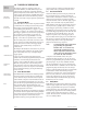
1.0 THEORY OF OPERATION THEORY OF OPERATION MECHANICAL INSTALLATION ELECTRICAL INSTALLATION PROGRAMMING USER MODE OPERATION TROUBLESHOOTING SPARE PARTS LISTING MAINTENANCE & SPECIFICATIONS INDEX The Mercury offers four operating modes for maximum flexibility in small OPL and Top Load washer laundry applications. Automatic Formula Selection may be used in all modes whenever a spare washer supply signal output is available that may be programmed to the second.
2.0 MECHANICAL INSTALLATION CAUTION: The Mercury dispensing system is intended to be installed by experienced installers in accordance with all applicable electrical and plumbing codes. Disconnect power to all laundry machine and dispensers during installation and/or any time the dispenser cabinet is opened. 2.1 Wall Mounting Unit To determine a suitable location to install the dispenser, keep the following in mind: Install close to product containers at a reasonable height for easy service access.
3.0 ELECTRICAL INSTALLATION THEORY OF OPERATION MECHANICAL INSTALLATION ELECTRICAL INSTALLATION PROGRAMMING USER MODE OPERATION TROUBLESHOOTING SPARE PARTS LISTING The Mercury is available in two different wiring versions: terminal block, or wiring cable. The following instructions apply to cable versions. Terminal Block versions include an additional wiring information label adjacent to the terminal blocks inside the unit enclosure.
4.0 USER MODE OPERATION The Mercury dispensers four modes of operation are described in this section. Automatic Mode runs each pump program (program = delay time + run time) upon qualified input to the respective signal input. When on (not set to 000), the Lockout Timer begins at start of first pump program (beginning of delay time). During this lockout period, no pump amount may run more than once regardless of the number of times the signal input occurs.
THEORY OF OPERATION Figure 4.0 MECHANICAL INSTALLATION User Mode Display Idle Home Screen Signal 1/Pump 1 On Signal 2/Pump 2 On Signal 3/Pump 3 On Running Home Screen Pump 1 On Pump 2 On Pump 3 On Blinking dash indicates Running Formula, all modes. (Also indicates Lockout when enabled.) ELECTRICAL INSTALLATION Total Loads 2 Sec User Functions Unit ID PROGRAMMING XX. = Version Info .
5.0 PROGRAMMING 5.1 Introduction Use the menu screen illustrations as a guide when learning to program the Mercury. We suggest that you power up a unit and become familiar with the programming steps in a quiet environment, with the manual, prior to the first installation. Use the Next key to move to all available main menu screens in Program Mode. 5.1.1 Key Descriptions Next Key-Move to the next item or task. User Mode: Move through the available User Mode screens.
THEORY OF OPERATION 5.3 Prime Pump “P-1” Press the Scroll Key to select pump number. Press the Enter Key to turn pump on. Press the Enter Key again to turn the pump off. Pump prime automatically ends after 5 minutes, if pump is left on. MECHANICAL INSTALLATION 5.4 Clear Load Counter “CLr” Every two seconds, the screen alternates between CLr and load count (all formulas). Press and hold the Enter key for two seconds to reset the Load Counter.
5.11 Exit Program Mode “End” Press the Enter key to exit Program Mode and return to User Mode. NOTE: To clear all values and restore factory settings, press and hold the Scroll key for two seconds, then press the Enter key (while still pressing the Scroll key). “FAC” will appear to indicate that you have restored factory settings and cleared the dispenser’s memory (including counter reset to zero). Press the Enter key again to return to User Mode. Figure 5.0 Figure 5.0.
6.0 TROUBLESHOOTING THEORY OF OPERATION MECHANICAL INSTALLATION Dead Unit (No Display) Troubleshooting 1. Verify Main Power (between 90 VAC and 249 VAC, 50/60 Hz) is present on Main Power Cable (or Terminals) and Power Switch (located behind cover in upper left corner) is On. Yes? Go to step 2. No? Restore Main Power source. 2.
7.0 SPARE PARTS LISTING THEORY OF OPERATION 1 2 MECHANICAL INSTALLATION ELECTRICAL INSTALLATION 4 PROGRAMMING 3 USER MODE OPERATION 5 SPARE PARTS LISTING 6 REF NO. PART NO. 1 13-07265-00 Power Supply 2 13-07264-01 Logic Circuit Board 3 13-06524-00 Pump Motor Detergent (2-Pin Plug) 4 13-06398-00 Pump Front, w/Captive Screw DESCRIPTION 5 13-07028-368 Pump Tube, Epdm, w/ 3/8" Barb, Ea.
8.0 MAINTENANCE & SPECIFICATIONS THEORY OF OPERATION MECHANICAL INSTALLATION ELECTRICAL INSTALLATION Routine maintenance includes keeping the dispenser wiped clean with a damp cloth and periodic Pump Tube replacement. NOTE: In the event of pump tube failure, always clean all pump part surfaces with a damp cloth to prevent possible damage from chemical attack. 8.1 Dimensions Size: 8" (20.3 cm) wide X 9" (22.2 cm) high X 6" (150.4 cm) deep Weight: 5.5 lbs. (2.47 kilos) Temperature: 120° F Maximum 8.
Index THEORY OF OPERATION A O Auto Formula Select Wiring 4 Automatic Mode 2, 5 Occurrence Mode 2, 5 Operating Modes 2 Operating Parameters “oP” 8 C Clear Load Counter “CLr” 8 Counting Loads 2 P H Password access to program mode 7 edit "PIN" 8 Password Edit “Pin” 8 Power Failure 5 Prevent false activation of pumps 2 Prime Pump “P-1” 8 Product levels 2 Program Mode Screens 9 Programming 7 Pump delays 2 numbers 2 product levels A & B 2 run time, setting 8 Pump Amount “P1A 8 Push Button Mode 2, 5 Hose