PRECAUTIONS WATER & ELECTRONICS DON'T MIX! Do not operate model in or around water. Never allow water, moisture, or other foreign materials to get inside the ESC (Electronic Speed Control). 4-10 CELLS (CYCLONE); 4-6 CELLS (ATOM) ONLY Never use more than 10 sub-C cells (1.2 volts DC/cell) in the Cyclone or 6 sub-C cells in the Atom’s main battery pack. MOTOR CAPACITORS REQUIRED Three 0.1µF (50V) ceramic capacitors must be properly installed on every motor to prevent radio interference.
CYCLONE & ATOM OWNER’S MANUAL The Novak Cyclone (#1765) and Atom (#1770) Programmable ESCs, are all-digital, microprocessor-based electronic speed controls which use advanced micro components to deliver the best possible performance with the smallest size and lightest weight. The following instructions will help provide you with troublefree speed control operation. These steps will allow your speed control to achieve maximum performance and minimize the chance of problems due to incorrect installation.
FEATURES LISTING The Cyclone and Atom ESCs are loaded with features, such as: • Highest motor control frequency (up to 23,400 Hz). • 256 discrete steps forward & 256 discrete steps braking for smoothest trigger response available (0.39% per step). • Adjustable minimum brake that can be set from 0% to 75% with the use of a simple adjustment pot. • Three different user-selectable profiles to suit the desired application (off-road, touring sedan, 1/12 scale, oval, etc.
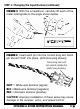
STEP 1: CHANGING THE INPUT HARNESS 1. The Cyclone and Atom ESCs include the Novak Input Plug System™ to convert the Futaba J style signal harness to be compatible with Airtronics/Sanwa (AIR), KO, Kyosho (KYO), and JR/Hitec/AIR Z (JR) receivers. Refer to Figures 1-5 NOTE: It is important that the metal locking tabs do not extend outside the plastic plug housing.
STEP 1: Changing the Input Harness (continued) FIGURE 3 With the screwdriver, carefully lift each of the metal locking tabs to the angle shown below. FIGURE 4 Insert each pin into the correct plug slot. Each pin should "click" into place. (Airtronics plug shown) The locking tab must not extend outside the plastic plug housing.
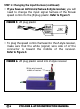
STEP 1: Changing the Input Harness (continued) • If you have an Airtronics/Sanwa Z-style receiver, you will need to change the input signal harness of the Novak speed control to the JR plug plastic. Refer to Figure 5 FIGURE 5 JR plug plastic • To plug the speed control harness into the Z-style receiver, make sure that the white (signal) wire side of of the connector is toward the middle of the receiver.
STEP 2: MOUNTING INSTRUCTIONS The following information will help ensure that the Atom and Cyclone perform at maximum efficiency, and will minimize the chances of overheating and radio interference. 1. DETERMINE THE BEST ESC MOUNTING LOCATION To prevent radio interference, the speed control should be positioned away from the receiver and antenna as shown in the Cyclone/Atom Hook-Up Photo (Figure 11). Choose a mounting position where the power wires will not obstruct movement of the T-Bar or suspension.
STEP 2: Mounting Instructions (continued) 5. INSTALL THE ANTENNA Mount the antenna as close to the receiver as possible. Trail any excess wire off the top of the antenna mast. NOTE: Do not cut or coil excess wire, or range will be reduced. STEP 3: HOOK-UP INSTRUCTIONS 1. INSTALL MOTOR CAPACITORS (Refer to Figure 7) Electric motors generate radio noise that can interfere with your receiver and cause radio problems. Included in the speed control's accessory kit are three 0.
STEP 3: Hook-Up Instructions (continued) 2. INSTALL SCHOTTKY DIODE (Refer to Figure 7) The Cyclone uses an internal Schottky diode, while the Atom does not. For added performance, it is recommended that an external Schottky diode be installed on all motors, and must be used with the Atom. This will increase the efficiency and reduce the operating temperature of the speed control. Solder the lead closest to the silver stripe on the Schottky to the POSITIVE (+) motor tab.
STEP 3: Hook-Up Instructions (continued) lead (short lead) marked with a stripe and minus (–) sign. The positive lead (long lead) is unmarked.
STEP 3: Hook-Up Instructions (continued) Make a small splice on the black and red power wires. Solder the power capacitor’s negative lead to the splice on the black power wire. Solder the power capacitor’s positive lead to the splice on the red power wire. Slide the included large heat shrink tubing over the capacitor and connection. This will protect the capacitor from vibration and the capacitor’s leads from short-circuiting.
STEP 3: Hook-Up Instructions (continued) To Install Power Wires: Tin the end of the power wires and the Solder Posts. Solder the power wires to their respective posts. The color designation for the wire is etched on the ESC’s case, next to the corresponding solder post. SOLDERING TIP: Be careful not to position the power wires over the transistor tabs.
STEP 3: Hook-Up Instructions (continued) pack connection) to desired length and strip about 1/4” of insulation off the end. Solder to positive tab of motor. 9. USING PLUGS FOR BATTERY & MOTOR CONNECTION High-quality/low-resistance connector plugs, such as Dean’s Ultra Plugs, can also be used to connect the motor and battery pack. Be sure to use connectors that can not be connected backwards, as this will damage the speed control.
STEP 4: TRANSMITTER ADJUSTMENTS BASIC TRANSMITTER ADJUSTMENTS 1. Set HIGH ATV or EPA to maximum setting. [Controls amount of throw from neutral to full throttle] 2. Set LOW ATV, EPA, or ATL to maximum. [Controls amount of throw from neutral to full brakes.] NOTE: Reduce this after performing One-Touch Set-Up to reduce amount of brakes. 3. Set EXPONENTIAL to zero. [Controls the linearity of the throttle channel] 4. Set THROTTLE CHANNEL TRIM to middle setting.
STEP 4: Transmitter Adjustments (continued) TRANSMITTER CHART ABBREVIATIONS CW Clockwise CCW Counter-Clockwise F Full throttle trigger position B Full brake trigger position AIRTRONICS CL-3PS FIRST: With the trigger in the brake position, set EPA/TH to 90%, then adjust the TH-EPA-L knob to full counter-clockwise position. EPA/TH (F/B) ARC-TH REV-TH TH-TRIM 140%/160% 0% NOR (Middle) NOTE: After speed control set-up, the TH-EPA-L knob will be used to reduce maximum push brake.
STEP 4: Transmitter Adjustments (continued) KO PROPO PRECIOUS SUB•TRIM(TH) REV. SW(TH) Trim: Pos(TH) TH: PUNCH(F/B) 0 REVE TH: HiPOT TH: BRAKE H100 B100 0% 0%/0% NOTE: After speed control set-up, TH-BRAKE will be used to adjust maximum push brake. KO PROPO MARS SUB•TRIM(TH) REVERSE(TH) Et2:Pos(TTrim) TH: PUNCH(F/B) 0 REVE TH: HiPOT Et4:Pos(BRAK) H100 100 0 0%/0% NOTE: After speed control set-up, Et4 will be used to adjust maximum push brake. FUTABA 3PJ SUB.TR TH.
STEP 5: SPEED CONTROL SET-UP Before beginning this step, the speed control should be connected to the receiver and to a charged battery pack (4-10 cells for the Cyclone, 4-6 cells for the Atom), and the transmitter should be adjusted according to Step 4. 1. TURN ON THE TRANSMITTER 2. TURN ON THE SPEED CONTROL Slide the ON/OFF switch to the ON position. 3.
STEP 5: Speed Control Set-Up (continued) This must be done as soon as the LED turns solid green to ensure that the speed control learns the Full Brake position. Moving the trigger gradually and/or hesitating after the status LED turns solid green may cause less than the Full Brake position to be learned. Hold the trigger there until the status LED blinks green. 7. RETURN TRANSMITTER’S THROTTLE TO NEUTRAL POSITION The status LED will turn solid red, indicating that proper programming has been completed.
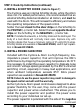
PROFILE Measurement Units 1 Stock 2 Drag Brake 3 Modified Ba Mi ad De Since drivers have their own racing preferences, the Cyclone & Atom are factory-programmed with three user-selectable profiles to choose from. This chart describes them. nd nim um Dr ive Br ak eF req ue nc Dr y ive Fre qu en cy STEP 6: THROTTLE PROFILE SELECTION % % KHz KHz 6 6 4 6.0 6.0 1.5 3.90 5.86 3.90 5.86 7.80 15.60 NOTE: These three profiles are not exclusive to the listed applications.
STEP 6: Throttle Profile Selection (continued) 5. After the status LED is finished blinking, press and release the 1-TOUCH button. This will select the next profile and the LED will blink the appropriate number of times to indicate which profile is selected. NOTE: After profile 3 has been selected, the selection process rolls over to profile 1. 6.
STEP 6: Throttle Profile Selection (continued) 256 Discrete Steps to Full Brake 50 256 Discrete Steps to Full Throttle 50 15% 20 20 10 TRIGGER Full Brake POSITION Minimum Minimum Brake [20%] Drive [10%] Neutral 10 % FULL DRIVE 100 100 DEADBAND % FULL BRAKE FIGURE 14 General Diagram of Minimum Brake, Dead Band and other parameters.
FET SERVO CONNECTION The Cyclone & Atom are wired for connecting a FET Servo. This type of servo requires a fourth wire connection. The fourth wire from the servo is connected to the small, blue 24-gauge silicone wire coming out of the ESC. In the Cyclone, this wire supplies 6 volts of power to the servo and is controlled by the speed control’s ON/OFF switch. In the Atom, this wire supplies battery voltage to the servo, and is also controlled by the speed control’s ON/OFF switch.
USING A RECEIVER BATTERY PACK The Cyclone & Atom do not require an external receiver battery pack for most racing situations. Built-in Radio Priority Circuitry™ provides complete control of the steering servo even after the main battery pack has "dumped" and can no longer provide the power required to operate the motor.
Installing Brake Lights (continued) TO CONNECT BRAKE LIGHTS TO THE CYCLONE Refer to Figure 16 1. Strip about 1/4" of insulation off both the small (26-gauge) red & black brake light wires that exit the side of the Cyclone. 2. Remove the insulation from the JST harness that is prestripped at the end of the wire and slip the heat shrink tubing over each wire. 3. Connect the JST harness to the brake light wires of the speed control by twisting or soldering the two wires.
Installing Brake Lights (continued) MOUNTING THE BRAKE LIGHT BRACKETS The brake light brackets can be mounted behind the taillight section of the car body, or onto most any vertical or horizontal surface on the chassis or body. • To mount the brackets to the taillight section, insert the screws through holes in the car body and into the screw openings in the bracket.
TROUBLE-SHOOTING GUIDE This section describes possible speed control problems, causes and solutions. For additional help, please call Novak Technical Assistance. Cyclone or Atom Will Not Program Properly • Too little transmitter throw—Increase the ATV/EPA setting to maximum. • Make sure ESC is plugged into the throttle channel of receiver. Check throttle channel operation with a servo. • ESC’s 1-TOUCH button not held long enough—Press and hold 1-TOUCH button until status LED turns solid red.
Trouble-Shooting Guide (continued) Other causes: • ESC is not set—Repeat One-Touch Set-Up process. • Check wiring and connections. Check operation of system without ESC. Receiver Glitches/Throttle Stutters During Acceleration • Motor capacitors broken or missing—Refer to STEP 3. • Receiver or antenna too close to speed control, power wires, battery, or motor—Refer to STEP 2. • Bad connections—Check wiring and connectors. • Excessive current to motor—Use a milder motor or smaller pinion gear.
SERVICE PROCEDURES PLEASE NOTE: Speed controls that operate normally when received will be charged a minimum service fee and return shipping/handling costs. Before sending in your speed control for service, it is important that you review the Trouble-Shooting Guide and all instructions. The speed control may appear to have failed when other problems exist in the system such as a defect in the transmitter, receiver or servo, incorrect adjustments/ installation.
Service Procedures (continued) WHAT TO SEND Completely fill out all of the information requested on the included SERVICE CARD and return it with your speed control. This will help ensure proper servicing of your product. It is not necessary to send the instruction manual, box or accessories. WARRANTY WORK For warranty work, you MUST CLAIM WARRANTY on the SERVICE CARD and attach a valid, dated receipt, or an invoice from previous service work.
Service Procedures (continued) HELPFUL INFORMATION YOU SHOULD KNOW: • CUSTOMER SERVICE HOURS (Pacific Standard Time) Monday-Thursday: 8 am - 5 pm Friday: 8 am - 4 pm (Closed every other Friday) PHONE: (714)* 833-8873 FAX: (714)* 833-1631 *Effective 4/18/98, area code will change to 949. • SEND UNITS TO: Novak Electronics, Inc. 18910 Teller Ave. Irvine, CA 92612 USA Attn: Service Department • WEBSITE ADDRESS: www.teamnovak.com e-mail: customersupport@teamnovak.
SPECIFICATIONS CYCLONE & ATOM SPECIFICATIONS SPECIFICATION CYCLONE ATOM Programmable ........................................ Yes ....................... Yes Discrete Steps (For/Rev) ........ 512 (256/256) ..... 512 (256/256) Input Voltage (1.2VDC/cell) ........... 4-10 cells ................ 4-6 cells Motor Limit ......................................... None .................... None Case Width (in/cm) ...................... 1.73/4.40 ............. 1.23/3.12 Case Depth (in/cm) ...................... 1.
PRODUCT WARRANTY Novak Electronics, Inc. guarantees the Cyclone & Atom to be free from defects in materials and workmanship for a period of 120 days from original date of purchase (verified by dated, itemized sales receipt). Warranty does not cover incorrect installation, components worn by use, damage from using more than 10 cells (1.
Keep Receiver and Antenna away from motor, servo, battery, and power wires. Trail excess wire off antenna mast. (Do not cut or coil) Twist motor wires to reduce Radio Frequency (RF) noise Black Power Wire (Battery negative) Three 0.1µF Capacitors (–) (+) (–) Input Harness Data Link™ LED Mount ON/OFF Switch where it will be easily accessible.