
Owner's manual


CYCLONE & ATOM INSTRUCTION MANUAL 5
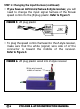
FIGURE 4 Insert each pin into the correct plug slot. Each
pin should "click" into place. (Airtronics plug shown)
WHT = White wire terminal (signal)
BLK = Black wire terminal (negative)
RED = Red wire terminal (positive)
CAUTION: Improper installation of these wires may cause
damage to the receiver, servo, and speed control.
STEP 1: Changing the Input Harness (continued)
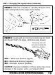
FIGURE 3 With the screwdriver, carefully lift each of the
metal locking tabs to the angle shown below.
The locking tab must
not extend outside the
plastic plug housing.