
Owner's manual


8 CYCLONE & ATOM INSTRUCTION MANUAL
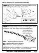
1. INSTALL MOTOR CAPACITORS (Refer to Figure 7)
Electric motors generate radio noise that can interfere with
your receiver and cause radio problems. Included in the speed
control's accessory kit are three 0.1µF (50V) non-polarized,
ceramic capacitors. These capacitors must be installed on
every motor to help reduce the noise generated by the motor
and also to prevent possible damage to the speed control.
Solder 0.1µF (50V) capacitors between:
• POSITIVE (+) motor tab & NEGATIVE (–) motor tab.
• POSITIVE (+) motor tab & GROUND tab*.
• NEGATIVE (–) motor tab & GROUND tab*.
STEP 2: Mounting Instructions (continued)
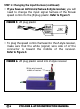
5. INSTALL THE ANTENNA
Mount the antenna as close to the receiver as possible. Trail
any excess wire off the top of the antenna mast.
NOTE: Do not cut or coil excess wire, or range will be reduced.
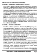
STEP 3: HOOK-UP INSTRUCTIONS
*If motor does not have ground
tab, solder to the motor can.
FIGURE 7
Negative (–) Motor Tab
0.1
µ
F
Capacitors
Schottky Diode
Positive (+) Motor Tab
Ground/Motor Can*
Continued