
User manual

- 12 -
UBZ-302
NOVATEK-ELECTRO
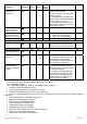
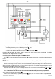
1 – Green LED “SETUP” – glows when the relay is in the mode of adjusting the parameters
2 – Green LED “LOAD” – glows then the output contacts of power relay are closed
3 – GreenLED “RELAY” – glows when output contacts of functional relay are closed
4 – Green LED “MMSP” – glows when UBZ-302 is operating in the mode with minimal number of setting parameters
5 – 3 DIGITS 7-SEGMENT LED INDICATOR:
shows the name of parameter that doesn’t belong to the list of minimal number of setting parameters
glows then the value of adjusted parameter is protected with the password of advanced user
glows when the UBZ-302 is in the advanced user setting mode
6 – 3 DIGITS 7-SEGMENT LED INDICATOR – shows the value of parameter
7 – Blue LED “EXCHANGE” – glows during the data exchange between the UBZ-302 and computer
8 – Red LED “FAULT”:
when power relay contacts are open – it glows then the UBZ-302 when some alarm situation detected (and
blinks if after the fault autoreclosing is allowed);
when power relay contacts are closed – it blinks when the motor is in the condition of the overload to maximal
current or the thermal overload condition but the turn OFF time not yet came
9 – socket for the connection of the UBZ-302 to computer by RS-232 protocol
10 – Green LED “ ”- glows when functional relay works in delta/star switching mode (paragraph 2.4.3.)
11 – Green LED “TR” – glows then functional relay works in Time relay mode
12 - Button
– scrolling to view the parameters values and listing the menus when adjusting the parameters
13 - Button
– scrolling to view the parameters values and listing the menus when adjusting the parameters
14 – Button “RES/MEM/SEL” – reset of parameter; saving parameter values in setting mode; switching in between
the groups of parameters in the view mode
15 – Button “SET”– turns ON the parameters setting mode
NOTES:
1 -
- in text star/delta
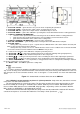
2 – In order to increase the reliability of the UBZ-302 for the input terminals of the power supply the terminals with the
step 7,5 mm are being used. Standard numeration of the terminals on the plastic housing of the UBZ-302 case does not
fully correspond to the real connection terminals. Thus on the Figure 2.1 some terminals are shown with intermediate
values.
Figure 1.1 - Control knobs and outer dimensions of the UBZ-302
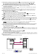
1.2.5.2. Maximal current protection on phases is 3 phase protection. It trips when one, two or three currents
reach some user defined threshold value.
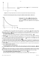
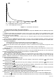
This type of protection has a time delay setting. This time delay could be fixed (some constant value) or have
the inverse relation of several types: standard inverse relation - SIT; very inverse relation - VIT or LTI; extreme
inverse relation - EIT; ultimate inverse relation-UIT, delay type R1) – dependency
curves are shown in APPEN-
DIX 1 (kindly see APPENDIX 1 in the bottom of this manual).
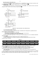
Maximal Current Protection with independent time-delay means that the motor will be switched OFF when the
current on one of phases exceed the threshold value. Time-delay is fixed. (Parameter “
i
=
t”)