
Manual

Controller N1200
NOVUS AUTOMATION 6 / 13
In order to operate appropriately, the controller needs a configuration
that is the definition of each one of the several parameters presented
by the controller. The user must be aware of the importance of each
parameter and for each one determine a valid condition or a valid
value.
Note: Since many parameters depend on the input type chosen,
it is recommended that the parameter
TYPE
be the first one to be
configured.
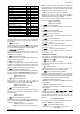
The parameters are grouped in levels according to their functionality
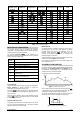
and operation easiness. The 7 levels of parameters are:
LEVEL ACCESS
1 - Operation Free access
2 - Tuning
Reserved access
3- R&S Programs
4- Alarms
5- Scale
6- I/Os
7- Calibration
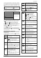
Table 5 – Cycles of Parameters
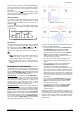
The parameters in the operation level have easy access through the
key
P
. The access deeper levels use the combination of keys:
(BACK) and
P
(PROG) pressed simultaneously
Press
P
to advance or
to retrocede parameters within a level. At
the end of each level, the controller returns to the operation level.
Keep pressing the
P
key to move fast forward in the level.
Alternatively, the controller returns to the operation level after
pressing the
key for 3 seconds
All configuration parameters are stored in protected memory. The
values are saved when the keys
P
or
are pressed after changing
a parameter value. The value of SP is saved upon pressing the
P
key or every 25 seconds.
DESCRIPTION OF THE PARAMETERS
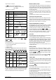
OPERATION CYCLE
To access the operation level parameters, press
P
until the desired
parameter is displays.
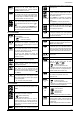
PV Indication
(Red Screen)
SP Indication
(Green Screen)
PV and SP indication – The upper display shows
the current value of PV. The lower display shows
the control SP value.
(trl
Control
Control Mode:
avto
- Means automatic control mode.
Man
– Means manual control mode.
(bumpless transfer between automatic and manual
control modes).
PV Indication
(Red Screen)
MV Indication
(Green Screen)
MANIPULATED VARIABLE VALUE (MV): The
upper display shows PV value and the lower display
shows the percentage of MV applied to the control
output. When in manual control,
the MV value can
be manually changed by the
and
keys.
When
in auto mode the MV value can only be viewed.
To distinguish the MV display from the SP display,
the MV is shown flashing intermittently.
E pr
Enable
Program
Execution of Program - Selects the ramp and
soak profile program to be executed.
0 - does not execute program
1 to 20
number of the program to be
executed
With enabled outputs (RUN = YES), the program
starts right after the program is selected.
p.seg
Screen for indication only. When a ramp and soak
program is active, this parameter shows the number
of the segment under execution, from 1 to 9.
t.seg
Screen for indication only. When a ramp and soak
program is in execution, it shows the remaining
time to the end of the current segment, in units of
time configured in the Pr.tb parameter.
rvn
Enables control outputs and alarms.
YES
- Outputs enables.
NO
- Outputs not enabled.
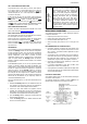
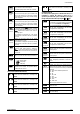
CYCLE OF TUNING
Atvn
Auto-tune
Defines the control strategy to be taken:
off
– Turned off. (no PID tuning)
Fast
–
Fast
automatic tuning.
Full
–More accurate automatic tuning.
self
– Precise + auto - adaptative tuning
rslf
–Forces one new precise automatic
precise + auto - adaptative tuning.
T9kt
- Forces one new precise automatic + auto
- adaptative tuning when Run = YES or controller
is turned on.
pb
Proportional
Band
PROPORTIONAL BAND - Value of the term P of
the control mode PID, in percentage of the
maximum span of the input type. Adjust of
between 0 and 500.0 %. Select zero for ON/OFF
control.
ir
Integral Rate
INTEGRAL RATE - Value of the term I of the PID
algorithm, in repetitions per minute (Reset).
Adjustable between 0 and 99.99.
Displayed only if proportional band ≠ 0.
dt
Derivative Time
DERIVATIVE TIME - Value of the term D of the
control mode PID, in seconds. Adjustable between
0 and 300.0 seconds.
Displayed only if proportional band ≠ 0.
(t
Cycle Time
Pulse Width Modulation (PWM) period in seconds.
Adjustable between 0.5 and 100.0 seconds.
Displayed only if proportional band ≠ 0.
kyst
Hysteresis
CONTROL HYSTERESIS (in engineering. units):
This parameter is only shown for ON / OFF control
(Pb=0).
Adjustable between 0
and the
measurement input type span.
ACt
Action
CONTROL ACTION: For Auto Mode only.
re
Control with reverse Action. Appropriate for
heating. Turns control output on when PV
is below SP.
dir
Control with direct Action. Appropriate for
cooling. Turns control output on when PV
is above SP.
Lbd.t
Loop break
detection time.
Time interval for the LBD function. Defines the
maximum interval of time for the PV to react to a
control command. In minutes
bias
BIAS: Offset for MV (manual reset). Range: -100
% to +100 %.
Allows adding a percentage value between -100 %
and +100 %. to the MV control output
The value 0 (zero) disables the function.
ovll
Output Low
Limit
Lower limit for the control output - Minimum
percentage value assumed by the control output
when in automatic mode and in PID.
Typically configured with 0 %. Default value: 0 %