
User Manual


NOVUS AUTOMATION 1/9
Controller N2000
UNIVERSAL PROCESS CONTROLLER – INSTRUCTIONS MANUAL – V2.1x C
PRESENTATION
The N2000 is a process controller incorporating a PID algorithm and
universal inputs (sensor and standard signals) and outputs (logical,
relay and analog outputs). It holds in one single instrument all de main
features that are needed for the vast majority of industrial processes.
SAFETY SUMMARY
The symbols below are used on the equipment and throughout this
document to draw the user’s attention to important operational and
safety information.
CAUTION or WARNING:
Read complete instructions prior to
installation and operation of the unit.
CAUTION or WARNING:
Electrical Shock Hazard
All safety related instructions that appear in the manual must be
observed to ensure personal safety and to prevent damage to either
the instrument or the system. If the instrument is used in a manner
not specified by the manufacturer, the protection provided by the
equipment may be impaired.
OVER-TEMPERATURE PROTECTION
When designing any control system it is essential to consider what
will happen if any part of the system should fail. In temperature
control applications the primary danger is one in which the heating
remains constantly on. In any application where physical injury or
destruction of equipment might occur, it is recommend to install an
independent protection equipment, with a separate temperature
sensor, to disable the heating circuit in case of overheating. Please
note that the alarm relays within the controller will not give protection
under all failure conditions.
Man 5001132
INSTALLATION
Insert the unit into the panel cut-out and slide the mounting clamp
from the rear to a firm grip at the panel.
RECOMMENDATIONS FOR INSTALLATION
• Input signal wires should be laid out away from power lines and
preferably inside grounded conduits.
• Instrument mains (line) supply should be suitable for this purpose
and should not be shared.
• In controlling and monitoring applications, possible consequences
of any system failure must be considered in advance. The internal alarm
relay does not warrant total protection.
• Use of RC filters (47 R and 100 nF, serial) are highly recommended
when driving solenoids, contactor coils or other inductive loads.
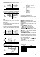
Figure 1 - Backpannel terminals
ELECTRICAL CONNECTIONS
All electrical connections are made to the screw terminals at the rear
of the controller. They accept wire sizes from 0.5 to 1.5 mm2 (16 to
22 AWG). The terminals should be tightened to a torque of 0.4 Nm
(3.5 lb in).
To minimize the pick-up of electrical noise, the low voltage DC
connections and the sensor input wiring should be routed away from
high-current power conductors. If this is impractical, use shielded
cables. In general, keep cable lengths to a minimum.
POWER WIRING
If high voltage is applied to
a low voltage input,
irreversible damage will
occur
Figure 2 – High and Low Voltage AC power wiring