
User Manual


Controller N2000
NOVUS AUTOMATION 4/9
ALARMS FUNCTION
The controller has 4 independent alarms. They can be programmed
to operate with nine different functions, represented in Table 3.
• Open sensor
It is activated whenever the input sensor is broken or disconnected.
• Event alarm
It activates alarm(s) in specific segments of the program. See item
6.2 in this manual.
• Resistance fail
Detects a heater broken condition, by monitoring the load current
when the control output is activated. This alarm function requires an
optional device (option 3). Details of the "resistance fail" option can
be found in a specific documentation that is sent with the product
when the option is purchased.
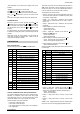
TYPE PROMPT
ACTION
Disabled
off
offoff
off
No active alarm. This output can be used as a digital
output to be set by the serial communication.
Sensor Break
(input Error)
ierr
ierrierr
ierr
Alarm will be ON if PV sensor breaks, input signal is
out of range or Pt100 is shorted.
Event Alarm
(ramp and
Soak)
rs
rsrs
rs
Can be activated at a specific segment of ramp and
soak program.
Detection
resistance fail
rfail
rfailrfail
rfail
Detects a heater broken condition
Low Alarm
lo
lolo
lo
SPAn
PV
High Alarm
k
kk
ki
ii
i
SPAn
PV
LOW
Differential
difl
difldifl
difl
SV
PV
SV
-
SPAn
positive SPAn
SV
PV
SV
-
SPAn
negative SPAn
HIGH
Differential
difk
difkdifk
difk
SV
PV
SV + SPAn
positive SPAn
SV
PV
SV + SPAn
negative SPAn
Differential
dif
difdif
dif
SV
PV
SV + SPAn
SV - SPAn
positive SPAn
SV
PV
SV
-
SPAn
SV + SPAn
negative SPAn
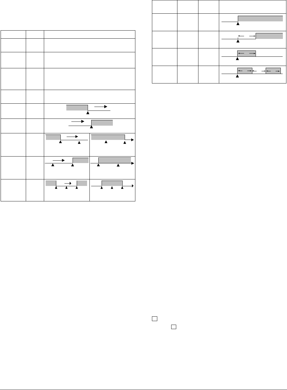
Table 3 - Alarm functions
Where SPAn means “SPA1
SPA1SPA1
SPA1”, “SPA2
SPA2SPA2
SPA2”, “SPA2
SPA2SPA2
SPA2” and “SPA4
SPA4SPA4
SPA4”.
• Minimum value
It is activated when the measured value is below the value defined in
the alarm Setpoint.
• Maximum value
It is activated when the measured value is above the value defined in
the alarm Setpoint.
• Differential (or Band)
In this function, the parameters “SPA1
SPA1SPA1
SPA1”, “SPA2
SPA2SPA2
SPA2” represent the PV
deviation as compared to the main SP.
In a positive deviation, the differential alarm will be triggered when
the measured value is out of the range defined in:
(SP – Deviation) and (SP + Deviation)
In a negative deviation, the differential alarm will be triggered when
the measured value is within the range defined above.
• Minimum differential
It is activated when the measured value is below the value defined in.
(SP - Deviation)
• Maximum differential
It is activated when the measured value is above the value defined in:
(SP + Deviation)
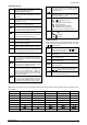
ALARM TIMER FUNCTIONS
Alarms 1 and 2 can be programmed to have timer functions. The 3
modes of operation are:
1- Pulse 2- delayed actuation 3- Oscillator
The desired function can be achieved programming the parameters
“A1t1
A1t1A1t1
A1t1”, “A1t2
A1t2A1t2
A1t2”, “A2t1
A2t1A2t1
A2t1” and “A2t2
A2t2A2t2
A2t2” (see Table 4).
The LEDs associated to the alarms will light when the alarm condition
is recognized, not following the actual state of the output, which may
be temporarily OFF because of the temporization.
ALARM
FUNCTION
T1 T2 ACTION
Normal 0 0
Alarm Event
Alarm
Output
Delayed 0
1 s to 6500
s
Alarm Event
Alarm
Output
T2
Pulse
1 s to 6500
s
0
Alarm Event
Alarm
Output
T1
Oscillator
1 s to 6500
s
1 s to 6500
s
Alarm Event
Alarm
Output
alarme
T1
T2
T1
Table 4 - Advanced Timer Alarm (for alarms 1 or 2)
ALARM INITIAL BLOCKING
The initial blocking option inhibits the alarm from being recognized if
an alarm condition is present when the controller is first energized.
The alarm will actuate only after the occurrence of a non alarm
condition followed by a new occurrence for the alarm.
The initial blocking is disabled for the sensor break alarm function.
SOFT START
Defines the time interval for the output to reach its maximum value
(100 %). The soft start value is programmed in “SfSt
SfStSfSt
SfSt”. See also
parameters “ovL
ovLovL
ovLL
LL
L” and “ovkL
ovkLovkL
ovkL”.
SQUARE ROOT EXTRACTION
Available when input type 19 is selected. The indicator displays the
square root of the current signal input applied to terminals 22 and 24.
REMOTE SETPOINT
The remote Setpoint (SP) is enabled by an external digital signal in
either I/O5 or I/O6, when programmed with the code 8 (Select remote
SP input).
An external resistor shunt of 100 Ω is required between the terminals
19 and 20, as shown in Figure 6.
ANALOG RETRANSMISSION OF PV AND SP
The analog output, when not used for control purposes, is available
for retransmitting the SV and SP values in 0-20 or 4-20 mA. This
analog output is electrically isolated from other inputs and outputs.
The analog output signal is scaleable, with the output range
determined by the values programmed in the parameters “SPLL
SPLLSPLL
SPLL” and
“SPkL
SPkLSPkL
SPkL”. To obtain a voltage output, connect a resistor shunt to the
current output terminals (terminal 13 and 14).
F
KEY AND DIGITAL INPUT (I/O6) FUNCTIONS
Both the
F
key and the I/O6 digital input can be programmed to
execute functions 7, 8, 9 and 10 shown in Table 2. The key function
is configured in parameter “
fFvn
fFvnfFvn
fFvn
”. The digital input function is
configured in parameter I/O6.
The digital input can also be configured for function 6: Auto/Manual
mode change.