
User Manual


Controller N2000
NOVUS AUTOMATION 5/9
KEY
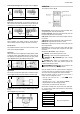
The
key in front panel executes function 6 of Table 2:
Auto/Manual mode change. Operation of this key is enabled in
parameter
aven
avenaven
aven
. The MAN indicator lights when the manual control
mode is selected.
EXTRA 24 VDC POWER SUPPLY – AUXILIAR P.S.
The controller provides a voltage power supply of 24 Vdc to excite
field transmitters with 25 mA current capacity. Available at the back
panel terminals 17 and 18.
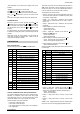
CONFIGURATION PARAMETERS
OPERATION CYCLE
PV Indication
(Red)
SV Indication
(Green)
PV AND SV INDICATION: The status display shows the
present value of PV (Process Variable). The parameter
display shows SV (Set Variable).
The status display shows “- - - -“ whenever PV exceeds the
maximum range or there is no signal at the input. In case of
hardware error the status display will show Ern
ErnErn
Ern, where n is the
error code.
avto
avtoavto
avto
CONTROL MODE: YES indicates automatic control mode
(closed loop, PID or ON/OFF). NO indicates manual control
mode (open loop). Bumpless transfer from auto ↔ to manual
mode is available. If in doubt program YES.
PV Indication
(Red)
MV Indication
(Green)
MANIPULATED VARIABLE VALUE (MV): The upper display
shows PV value and the lower display shows the percentage
of MV applied to the control output. When in manual control
the MV value can be manually changed. When in auto mode
the MV value can only be viewed.
To distinguish the MV display from the SV display, the MV is
shown flashing intermittently.
Pr n
Pr nPr n
Pr n
RAMP AND SOAK PROGRAM SELECTION: Selects the
ramp and soak program to be executed (7 programs
possible). Refer to chapter 7 for R&S description.
rvn
rvnrvn
rvn
CONTROL ENABLE: YES means that the control output and
alarms are enabled and NO means they are disabled.
AUTO TUNING CYCLE
atvn
atvnatvn
atvn
AUTO-TUNE: YES enables the auto tuning of the PID
parameters and NO disables it.
Pb
PbPb
Pb
PROPORTIONAL BAND: Percentage of maximum input span.
0 to 500 %. Select zero for ON / OFF control.
xyst
xystxyst
xyst
CONTROL HYSTERESIS (in engIneering. units): This
parameter is only shown for ON / OFF control (Pb=0).
‘ ir‘
‘ ir‘‘ ir‘
‘ ir‘
INTEGRAL RATE: Integral time constant in repetitions per
minute (Reset).
dt
dtdt
dt
DERIVATIVE TIME: Derivative time constant, in seconds.
(t
(t(t
(t
CYCLE TIME: PWM period in seconds. Can only be viewed if
proportional band is other than zero.
act
actact
act
CONTROL ACTION: For Auto Mode only.
•
rE
rErE
rE Reverse Action usually used for heating.
•
dir
dirdir
dir Direct Action usually used for cooling.
bias
biasbias
bias
Offset for MV (manual reset). Range: -100 % to +100 %.
Default value: 0.
ovll
ovllovll
ovll
OUTPUT LOW LIMIT: minimum percentage value for MV
(Manipulated Variable) when in automatic control and PID.
Default value: 0.0 %
ovxl
ovxlovxl
ovxl
OUTPUT HIGH LIMIT: Maximum percentage value for MV
when in automatic control and PID. Default value: 100.0%
sfst
sfstsfst
sfst
SOFT START: Time in seconds during which the controller
limits the MV value progressively from 0 to 100 %. It is
enabled at power up or when the control output is activated.
If in doubt set zero.
Sp.a1
Sp.a1 Sp.a1
Sp.a1
Sp.a2
Sp.a2 Sp.a2
Sp.a2
Sp.a3
Sp.a3 Sp.a3
Sp.a3
Sp.a4
Sp.a4Sp.a4
Sp.a4
ALARM PRESET: Tripping point for alarm 1, 2, 3 and 4.
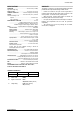
RAMP AND SOAK PROFILE PROGRAMMING CYCLE
tbas
tbastbas
tbas
TIME BASE: Selects the time base for the ramp and soak.
Valid for all profile programs.
0
0 0
0 - PT1 to PT7 values are in seconds;
1
11
1 - PT1 to PT7 values are in minutes;
Pr n
Pr nPr n
Pr n
PROGRAM TO BE VIEWED: Selects the ramp and soak
profile program to be edited/viewed in the following cycle
prompts (7 programs available).
ptol
ptolptol
ptol
RAMP AND SOAK TOLERANCE: maximum deviation
between PV and SV. Whenever this deviation is exceeded
the time counter is halted until deviation lowers to within the
tolerance. Set zero to disable this function.
Psp0
Psp0Psp0
Psp0
Psp7
Psp7Psp7
Psp7
RAMP AND SOAK SET POINTS (0 to 7): Set of 8 SV values
which define the ramp and soak profile segments. See also
PT1 to 7 and PE1 to 7 below.
Pt1
Pt1Pt1
Pt1
Pt7
Pt7Pt7
Pt7
RAMP AND SOAK SEGMENTS TIME (1 to 7): Set of 7 time
intervals in minutes or seconds (9999 max.) for the 7
segments of the ramp and soak program.
Pe1
Pe1Pe1
Pe1
Pe7
Pe7Pe7
Pe7
RAMP AND SOAK EVENT (1 to 7): Set of 7 values that
define which alarms must be activated during a ramp and
soak program segment. Alarm function depends on “rS
rSrS
rS”
setting (Table 3).
lp
lplp
lp
LINK TO PROGRAM: Number of the next profile program to
be linked to follow the current profile. Profiles can be linked to
make larger programs of up to 49 segments.
ALARM CYCLE
Fva1
Fva1Fva1
Fva1
ALARM 1 FUNCTION: Select options from Table 3.
Fva2
Fva2Fva2
Fva2
ALARM 2 FUNCTION: Select options from Table 3.
Fva3
Fva3Fva3
Fva3
ALARM 3 FUNCTION: Select options from Table 3.
Fva4
Fva4Fva4
Fva4
ALARM 4 FUNCTION: Select options from Table 3.
bla1
bla1 bla1
bla1
bla2
bla2 bla2
bla2
bla3
bla3 bla3
bla3
bla4
bla4bla4
bla4
ALARM BLOCK 1 TO 4: This function blocks the alarm at
power-up when the units is first energized.
YES enables and NO inhibits this blocking function. When
enabled the alarm will not be active at power-up waiting for
PV (Process Variable) to reach a non-alarm situation. From
this point on the alarm will be free to actuate should a new
alarm situation occur.
xya1
xya1xya1
xya1
ALARM 1 HYSTERESIS: Defines the differential range
between the PV value at which the alarm is turned on and
the value at which it is turned off (in engineering units).
xya2
xya2xya2
xya2
ALARM 2 HYSTERESIS: Same as above.
xya3
xya3xya3
xya3
ALARM 3 HYSTERESIS: Same as above.
xya4
xya4xya4
xya4
ALARM 4 HYSTERESIS: Same as above.
A1t1
A1t1A1t1
A1t1
ALARM 1 TIME 1: Defines the time (6500 sec. max.) during
which the alarm 1 output will be ON when alarm 1 is active.
Program zero to disable this function.
A1t2
A1t2A1t2
A1t2
ALARM 1 TIME 2: Defines the OFF state time for the alarm
1 output, after being ON during the time selected on ALARM
1 TIME 1. Program zero to disable this function.
A2t1
A2t1A2t1
A2t1
ALARM 2 TIME 1: Defines the time (6500 sec. max.) during
which the alarm 1 output will be ON when alarm 1 is active.
Program zero to disable this function
A2t2
A2t2A2t2
A2t2
ALARM 2 TIME 2: Defines the time during which the alarm 2
output will be, after being ON during the time selected on
ALARM 2 TIME 1. Program zero to disable this function.
Table 4 shows the advanced features that can be achieved
with these time functions.