
Instruction Manual


NOVUS AUTOMATION 1/9
Controller N2000S
UNIVERSAL PROCESS CONTROLLER – INSTRUCTIONS MANUAL – V2.1x
SAFETY SUMMARY
The symbols below are used on the equipment and throughout this
document to draw the user’s attention to important operational and
safety information.
CAUTION OR WARNING:
Read complete instructions prior to
installation and operation of the
unit.
CAUTION OR WARNING:
Electrical Shock Hazard
All safety related instructions that appear in the manual must be
observed to ensure personal safety and to prevent damage to either
the instrument or the system. If the instrument is used in a manner
not specified by the manufacturer, the protection provided by the
equipment may be impaired.
INTRODUCTION
N2000S is a controller for servo positioners with two control relays:
one to open and other to close the valve (or damper). Moreover, it
has an analog output that can be programmed to control or retransmit
input or setpoint signals. Its universal input accepts most industry
manufactured sensors and signals.
Configuration can be entirely achieved through the keyboard, no
circuit changes are required. Selection of input and output type,
alarms configuration, and other especial functions are accessed and
programmed through the frontal panel.
It is important that you read the manual thoroughly before using the
controller. Be sure the manual corresponds to your instrument (the
number of the software version can be seen when the controller is
turned on).
CHARACTERISTICS
• Sensor break protection in any condition; Universal multi-sensor
input without hardware change;
• Potentiometer input for current position reading;
• Auto-tuning of PID parameters;
• Control outputs: relays;
• Automatic/Manual “bumpless” transfer;
• Two alarm outputs; functions: minimum, maximum, differential
(deviation), open sensor and event. Two-alarm temporization;
• 4-20 mA or 0-20 mA analog output for Process Variable (PV) or
SetPoint (SP) retransmission;
• 4-function digital input;
• Ramp and soak with 7 programs of 7 segments with linking
capability;
• RS-485 serial communication; RTU MODBUS protocol;
• Configuration protection;
PRESENTATION / OPERATION
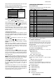
The controller frontal panel is shown in Figure 1:
Figure 1 – Frontal panel
PV/Programming Display: Shows the PV value. When in
programming mode, shows the parameter name.
SP/Parameters Display: Shows the SP and other programmable
parameter values of the controller.
COM Indicator: Flashes when data is exchanged with the external
environment.
TUNE Indicator: Lights during automatic tuning.
MAN Indicator: Indicates that the controller is in the manual control
mode.
RUN Indicator: Indicates that the controller is active, with control and
alarm outputs enabled.
OUT Indicator: When the analog output (0-20 mA or 4-20 mA) is set
for controlling actions the indicator lights continuously.
A1, A2 Indicators: Indicates the respective alarm status.
A3 Indicators: Indicates the valve (I/O3) opening output status.
A4 Indicators: Indicates the valve/dumper (I/O4) closing output status.
P
PROG key: Shows the controller programmable parameters.
BACK Key: ReReturns to the previous parameter shown in the
parameter display.
Increase and
Decrease keys: Change the parameter values.
Auto/Man key: Shortcut for automatic/manual control selection.
Alternates the control mode between automatic and manual each
time the key is pressed.
F
Programmable Function Key: Can be assigned to the special
functions described for the f.fvnc
f.fvncf.fvnc
f.fvnc parameter.
When the controller is turned on, its firmware version is displayed for
3 seconds, after that the controller starts operating normally. The PV
and SV values are displayed in the upper and lower displays
respectively. Outputs are enabled at this moment as well.
The relay associated to the valve closing is activated during the time
required for the complete valve to close (see parameter “Ser.t
Ser.tSer.t
Ser.t) so
that the controller starts operating with a known reference.
To run smoothly, the controller requires some basic configuration:
• Input type (Thermocouples, Pt100, 4-20 mA, etc.).
• Control setpoint value (SP).
• Control output type (relays, 0-20 mA, pulse).
• PID parameters (or hysteretic for ON / OFF control).