
Instruction Manual


Controller N2000S
NOVUS AUTOMATION
7/9
CALLIBRATION CYCLE
All input and output types are factory calibrated. Recalibration is
not recommended. If necessary, recalibration must be
performed by specialized personnel. If this cycle is accessed by
mistake, do not press
or
keys, go all through the prompts
up to the operation cycle is reached again.
Inl(
Inl(Inl(
Inl(
(input Low Calibration) – INPUT OFFSET CALIBRATION:
Makes possible to calibrate the PV offset. To change one
digit, press
or
as many times as necessary.
Inx(
Inx(Inx(
Inx(
(input High Calibration) – INPUT SPAN CALIBRATION
(gain): Makes possible to calibrate the PV offset.
Ovll
OvllOvll
Ovll
(output Low Calibration) – OUTPUT LOW CALIBRATION:
Value for current output low calibration (offset).
Ovx(
Ovx(Ovx(
Ovx(
(output High Calibration) – OUTPUT HIGH CALIBRATION:
Value for current output high calibration.
(j
(j (j
(j l
ll
l
COLD JUNCTION OFFSET CALIBRATION: Sets the cold
junction offset calibration.
Potl
PotlPotl
Potl
POTENTIOMETER LOW CALIBRATION. To change one
digit, press
and
as many times as necessary.
Potx
PotxPotx
Potx
POTENTIOMETER HIGH CALIBRATION – End of scale
calibration of the potentiometer.
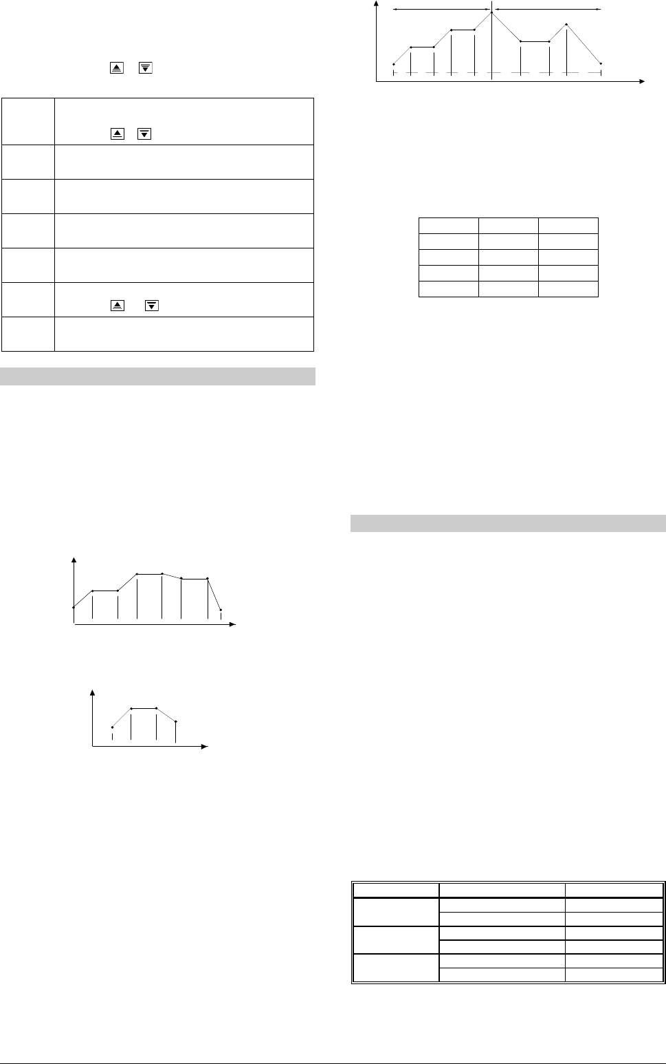
RAMP AND SOAK PROGRAM
This feature allows for the elaboration of a behavior profile for the
process. Each program is composed of a set of up to 7 segments,
named RAMP AND SOAK PROGRAM, defined by SP values and
time intervals.
When the program is defined and runs, the controller starts to
automatically generate the SP according to the program.
At the end of the program execution, the controller turns the control
output off (“rvn
rvnrvn
rvn”= no).
Up to 7 different programs of ramp and soak can be created. The
figure below shows an example of the program:
SP
tim e
T1
T2
T3
T4
T5
SP0
SP1
SP2
SP3
SP4
SP5
SP6
SP7
T6
T7
Figure 8 – Example of the ramp and soak program.
To execute a profile with fewer segments, set 0 (zero) for the time
intervals that follow the last segment to be executed.
SP
time
T1
T2
T3
SP0
SP1
SP2
SP3
T4=0
Figure 9 – Example of a program with a few segments
The tolerance function of the “PtoL
PtoLPtoL
PtoL” defines the maximum deviation
between PV and SP during the program execution. If this deviation is
exceeded, the program will be interrupted until the deviation falls
within the tolerance range (regardless of time). Programming 0 (zero)
at this prompt disables the tolerance; the profile execution will not be
halted even if PV does not follow SP (only considers time).
LINK OF PROGRAMS
It is possible to create a more complex program, with up to 49
segments, joining the seven programs. This way, at the end of a
program execution the controller immediately starts to run another
one.
When a program is created, it must be defined in the “LP
LPLP
LP" screen
whether there will be or not another program.
To make the controller run a given program or many programs
continuously, it is only necessary to link a program to itself or the last
program to the first.
SP
time
T1
T2
T3
T4
T5
T1
T2
T3
T4
SP0
SP1
SP2
SP3
SP4
SP5 / SP0
SP1
SP2
SP3
SP4
Prog 1
Prog 2
Figure 10 – Example program 1 and 2 linked (interconnected).
EVENT ALARM
This function makes possible to program the activation of alarms in
specific segments of a program.
For such, alarms must have their function set as “rS
rSrS
rS “ and be
programmed in “ PE1
PE1PE1
PE1“ to “ PE7
PE7PE7
PE7“ according to Table 6. The number
programmed in the event prompt defines the alarms to be activated.
CODE ALARM 1 ALARM 2
0
1 X
2 X
3 X X
Table 6 – Event values for ramps and soaks
In order to configure a ramp and soak program:
•
Tolerance values, SPs, time and event should be programmed.
•
If an alarm will be used with the event function, set up its function
to Event Alarm.
•
Set control mode to automatic.
•
Enable program execution in “ rS
rSrS
rS “ screen.
•
Start the control at the “rvn
rvnrvn
rvn” prompt.
Before executing the program the controller waits for PV to reach the
initial setpoint (“SP0
SP0SP0
SP0”). Should any power failure occur the controller
resumes at the beginning of the segment it was running.
AUTO TUNING OF PID PARAMETERS
During auto tune the process is controlled in ON / OFF mode at the
programmed SP. Depending on the process features, large
oscillations above and below SP may occur. Auto tune may take
several minutes to be concluded in some processes.
The recommended procedure is as it follows:
•
Disable the control output at the “rvn
rvnrvn
rvn” prompt..
•
Select auto mode operation at the “Avto
AvtoAvto
Avto” prompt.
•
Select a value different form zero for the proportional band.
•
Disable the soft-start function
•
Disable the ramp and soak function and program a new PV value
other than the present PV (close to the desired set point).
•
Enable auto tuning at the “Atvn
AtvnAtvn
Atvn” prompt.
•
Enable the control at the “rvn” screen.
During the auto tune procedure the TUNE indication will remain on.
For the control output with relays or current pulse, automatic tune
calculates the highest possible value for the PWM period. This value
can be reduced in cases of low instability. For a relay of solid state,
reduction to 1 second is recommended.
If the automatic tune does not result a satisfactory control, refer to
Table 7 for manual fine tuning procedure.
PARAMETER PROBLEM SOLUTION
Proportional band Slow response Decrease
Large oscillation Increase
Integral rate Slow response Increase
Large oscillation Decrease
Derivative time Slow response or instability Decrease
Large oscillation Increase
Table 7 – Suggestions for manual tuning of PID parameters