
User Manual


NOVUS AUTOMATION 1/9
Controller
N3000
UNIVERS
AL PROCESS CONTROLLER – INSTRUCTIONS MANUAL – V2.1x C
SAFETY SUMMARY
The symbols below are used on the equipment and throughout this
document to draw the user’s attention to important operational and
safety information.
CAUTION OR WARNING:
Read complete instructions prior to
installation and operation of the
unit.
CAUTION OR WARNING:
Electrical Shoc k Hazard
All safety related instructions that appear in the manual must be
observed to ensure personal safety and to prevent damage to either
the instrument or the system. If the instrument is used in a manner
not specified by the manufacturer, the protection provided by the
equipment may be impaired.
INTRODUCTION
The N3000 is a proces s controller incorporating a PID al gorithm and
universal inputs (sensor and standard signals) and outputs (logical,
relay and analog outputs). It holds in one single instrument all de
main features that are needed for the vast majority of industrial
processes.
OVER-TEMPERATURE PROTECTION
When designing any control system it is essential to consider what
will happen if any part of the system should fail. In temperature
control applications the primary danger is one in which the heating
remains constantly on. In any application where physical injury or
destruction of equipment might occur, it is recommend to install an
independent protection equipment, with a separate temperature
sensor, to disable the heating circuit in case of overheating. Please
note that the alarm relays within the controll er will not giv e protection
under all failure conditions.
CONFIGURATION
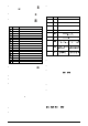
INPUT TYPE SELECTION
Select the input type (in parameter “
tYPE
”) from Table 1 below.
TYPE
CODE
CHARACTERISTICS
J
0
range: -50 to 760 °C (-58 to 1400 ºF)
K
1
range: -90 to 1370 °C (-130 to 2498 ºF)
T
2
range: -100 to 400 °C (-148 to 752 ºF)
N
3
range: -90 a 1300 °C (-130 a 2372 º F)
R
4
range: 0 a 1760 °C (32 a 3200 ºF)
S
5
range: 0 t o 1760 ° C (32 to 3200 ºF)
Pt100
6
range: -199.9 to 530. 0 ° C (-328.0 to 986.0 ºF)
Pt100
7
range: -200 t o 530 ° C (-328 to 986 º F)
4-20 mA
8
J linearization. Pr ogrammable r ange: -110 to 760 ° C
4-20 mA
9
K linearizat ion. Programmable r ange: -150 t o 1370 ° C
4-20 mA
10
T linearization. Pr ogrammable r ange: -160 to 400 ° C
4-20 mA
11
N Linearization. Programmable range: -90 a 1370 °C
4-20 mA
12
R Linearizati on. Program m able range: 0 a 1760 ° C
4-20 mA
13
S linearizat ion. Programmable r ange: 0 to 1760 °C
4-20 mA
14
Pt100 li neariz ation. Prog. Range:-200.0 to 530.0 °C
4-20 mA
15
Pt100 li neariz ation Pr og. Range:-200 to 530 °C
0 to 50 mV
16
Linear. Programmable indication -1999 to 9999
4-20 mA
17
Linear. Programmable indication -1999 to 9999
0 to 5 Vdc
18
Linear. Programmable indication -1999 to 9999
4 to 20 mA
19
Square Root Extr action
Table 1 - Input Types
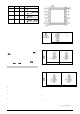
OUTPUTS, ALARMS AND DIGITAL INPUTS CONFIGURATION
The controller input/output channels can assume multiple functions,
depending on configuration: control output, alarm output, digital
output, digital input, and PV or SV analog retransmission. These
channels are identified as I/O1, I/O2, I/O3, I/O4, I/O 5 and I/O6.
The basic controller model comes loaded with:
• I/O1 and I/O2 - SPDT relay output;
• I/O3 and I/O4 – SPST relay output;
• I/O5 - analog output (0-20 or 4-20 mA), pulse 10 V max, digital I/O;
• I/O6 – Digital Input;
The function c ode of each I/O can be sel ected among the options on
Table 2. Only valid function codes are displayed for each I/O (for
example, I/O1, whic h is a relay , can be configured wi th functions 0 to
5 only; on the other hand, I/05 can perform all 16 functions).
The description for the functions follows:
• CODE 0 - No function. The I/O channel programmed with code 0
will not be used by the controller. It is available to be used by serial
communication as digital output.
• CODES 1 to 4 - Alarm output - Available for all I/O channels
(except I/O6). The selected channel can be used as output to
Alarms 1 to 4.
• CODE 6 - Digital input - Standard for I/O5 and I/O6.
Closed: Manual control
Opened: Automatic control