
User Manual


Controller N3000
NOVUS AUTOMATION 6/11
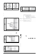
CYCLE ACCESS
1- Operation Free access parameters
2- Tuning
Reserved acc ess param eters
3- R&S Program
4- Alarms
5- Input Configuration
6- I/Os
7- Calibration
The parameters in the operation level (1
st
level) are easily accessed
through the
P
key. The access deeper levels use the combination of
Keys:
(BACK) and
P
(PROG) pressed simultaneously
Press
P
to advance or
to retrocede parameters within a level.
At the end of each level, the controll er returns to the operation l evel.
Keep pressing the
P
key to move fast forward in the level.
Alternatively, the controller returns to the operation level after
pressing the
key for 3 seconds.
All configuration parameters are stored in protected memory. The
values are sav ed when the keys
P
or
are pressed after changi ng
a parameter value. The value of SP is saved upon pressing the
P
key or every 25 seconds.
PROTECTION OF CONFIGURATION
The controller provides means for protecting the parameters
configurations, not allowing modifications to the parameters values,
avoiding tampering or improper manipulation.
The parameter Protection (
PROt
), in the Calibration level,
determines the protection strategy, limiting the access to particular
levels, as shown by the table below.
Protection
level
Protected cycles
1 Only the Calibration level is protected.
2
I/Os and Calibration levels.
3
Tuning, I/Os and Calibration levels.
4
Alarm, Tuning, I/Os and Calibration levels.
5
Programs, Alarm, Tuning, I/Os and Calibration
levels.
6
Tuning, Programs, Alarm, Input, I/Os and
Calibration levels.
7
Operation (except SP), Tuning, Programs, Alarm,
input, I/Os and Calibration levels.
8
Operation, Tuning, Programs, Alarm, Input, I/Os
and Calibration levels.
Table 7 – Levels of Protection for the Configuration
Access Password:
The protected lev els, when acc essed, request the user to provide the
Access Password for granting permission to change the
configuration of the parameters on these cycles.
The prompt
PASS
precedes the parameters on the protected levels.
If no pass word i s entered, the parameters of the protec ted cy cl es can
only be visualized.
The Access Code is defined by the user in the parameter Password
Change (
PAS.(
), present in the Calibration level. The factory default
for the password code is 1111.
Protection of the access code
The protection system built into the controller blocks for 10 minutes
the access to protected parameters after 5 consecutive frustrated
attempts of guessing the correct password.
Master Password
The Master Password is intended for allowing the user to define a
new password in the event of it being forgotten. The Master
Password doesn’t grant access to all parameters, only to the
Password Change parameter (
PAS(
). After defining the new
password, the protected parameters may be ac ces sed (and modi fi ed)
using this new password.
The master password i s made up by the last three digi ts of the serial
number of the controller added to the number 9000.
As an example, for the equipment with serial number 07154321, the
master password is 9 3 2 1.
CONFIGURATION PARAMETERS
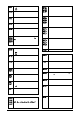
OPERATION CYCLE
PV Indication
(Red )
SV Indication
(Green)
PV / SP indication- The upper display shows the
current value of PV. The lower display shows the
control SP value.
Avto
Control
Contr ol Mode:
Yes
-Means automatic control mode.
no
-Means manual control mode.
Bumpless transfer between automatic and manual.
PV Indication
(Red )
MV Indication
(Green)
Screen PV and MV: The upper display shows PV
value and the lower display shows the percentage of
MV applied to the control output. When in manual
control t he MV value can be manuall y changed. When
in auto mode the MV value can only be viewed.
To distinguish the MV display from the SV display,
the MV is shown flashing intermittently.
Pr n
Program
number
Execution of Program - Selects the ramp and soak
profile program to be executed.
0 -does not execute program
1 a 7 -number of the program to be executed
p.seg
Indicati
ve screen. Shows the current segments
number of the running program.
t.seg
Indicative screen. Shows the current segments
remaining time.
rvn
Control Enable:
YES -means that the control output and alarms
are enabled.
NO -means they are disabled.
AUTO TUNING CYCLE
atvn
Auto Tune: Habilita a sintonia automática dos
parâmetros PID.
YES
-Auto-tune enable
NO
-Do not execute auto tune
Pb
Proportional Band - Percentage of
maximum input
span. Select zero for ON / OFF control.
ir
Integral Rate
‘
Value of the term I
of the PID algorithm, in repetitions
per minute.
Displayed only if proportional band ≠ 0.
Dt
Derivative
Time
Derivative Time - Value of the term D
of the control
mode PID, in seconds.
Displayed only if proportional band ≠ 0.
(t
Cycle Time
Pulse Width Modulation (PWM) period in seconds.
Displayed only if proportional band ≠ 0.
Xyst
Hysteresis
Control Hysterisis:
This parameter is only shown for
ON / OFF control.
Displayed only if proportional band = 0.