
Manual


DigiRail-VA
NOVUS AUTOAMTION 17/19
MODBUS COMMANDS AND REGISTERS TABLE
The DigiRail-VA accepts some Modbus commands that are sent to its Modbus’ own address, operating as a network
slave. Commands forwarded to other slaves (routing) will be sent in a transparent way. The following listed Modbus RTU
commands (functions) are implemented, and these are interpreted by DigiRail-VA. For further information about each
command and the Modbus protocol in general, access the website www.modbus.org
.
SUPPORTED MODBUS COMMANDS
READ HOLDING REGISTERS – 03H
This command can be used to read a value of one or up to the maximum consecutive holding registers, as shown in the
“Table of Holding Registers”.
WRITE SINGLE REGISTER – 06H
This command can be used to write on a holding register, as shown in the “Table of Holding Registers”.
WRITE MULTIPLE REGISTERS – 16H
This command can be used to write in multiple holding registers, as shown in the “Table of Holding Registers”.
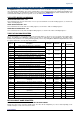
TABLE OF HOLDING REGISTERS
The specified addresses correspond to the low level physical addresses, where zero (0) corresponds to the address PLC
40001. The Minimum and Maximum columns have a range of valid values for each parameter. The R/W column
indicates if the parameter is for reading and writing (R/W) or if it is only reading ® The Mnemonic SuperView states what
the register mnemonic is for in the SuperView software.
Address Description Minimum Maximum R/W
Mnemonic
SuperView
0
RMS Voltage (floating point – word high)
0.0 +3.4e+38 R
1
Voltage RMS (floating point – word low)
2
Current RMS (floating point – word high)
0.0 +3.4e+38 R
3
Current RMS (floating point – word low)
8
Active Power / real power (floating point – word high)
0.0 +3.4e+38 R
9
Active Power / real power (floating point – word low)
10
Apparent power (floating point – word high)
0.0 +3.4e+38 R
11
Apparent power (floating point – word low)
12
Reactive power (floating point – word high)
0.0 +3.4e+38 R
13
Reactive power (floating point – word low)
14
Power factor (floating point – word high)
-1.0 R
15
Power factor (floating point – word low)
16
Frequency (floating point – word high)
0.0 +3.4e+38 R
17
Frequency (floating point – word low)
20
Voltage RMS x 10 (integer 16 bits unsigned)
0 65535 R VoltageRMS
21
Current RMS x 100 (integer 16 bits unsigned)
0 65535 R CurrentRMS
22
Maximum peak voltage x 10 (integer 16 bits unsigned)
0 65535 R MaxVoltagePeak
23
Maximum peak current x 100 (integer 16 bits unsigned)
0 65535 R MaxCurrentPeak
24
Active Power (real power) x 10 (integer 16 bits
unsigned)
0 65535 R ActivePower
25
Apparent power x 10 (integer 16 bits unsigned)
0 65535 R ApparentPower
26
Reactive power x 10 (integer 16 bits unsigned)
0 65535 R ReactivePower
27
Power factor x 1000 (integer 16 bits signed)
-1000 1000 R PowerFactor
28
Frequency x 10 (integer 16 bits unsigned)
0 650 R Frequency
31
Sign of the Reactive power (0 = inductive, 1 =
capacitive)
0 1 R LeadLag
200
Serial number (word high)
0 65535 R SerialNumber_H
201
Serial number (word low)
0 65535 R SerialNumber_L
202
Firmware Version
0 999 R FirmwareVersion
DETAILS ABOUT SOME REGISTERS
REGISTERS 20 TO 28 – MEASUREMENT VALUE IN INTEGER FORMAT
Reports the value of the respective variable input. The value will be multiplied by 10, 100 or 1000 depending on the
variable. Example: a value of 217.8 reads as 2178.