
Manual

INSTALLATION
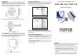
The TEMP-DM (Duct Mount) model transmitter should be installed with a flange.
This flange is first screwed onto the duct wall and the transmitter probe is then
inserted into the flange central hole and locked. Figure 05 below shows flange
dimensions and holes. Available in stainless steel or polyamide 6.6.
Figure 04 – Mounting flange for TEMP-DM.
The probe is made in stainless steel, with standard lengths of 150 mm and 250 mm.
Figure 05 - Model TEMP-DM dimensions.
The model TEMP-WM (Wall Mount) was designed to be mounted directly onto a wall.
With the cover off, the user can access the 2 fixing points and the signal connector, as
shown in Figure 07. The transmitter sensor capsule must be placed faced down in
order to assure the specified accuracy and protection level.
Figure 07 - TEMP-WM fixing holes and housing dimensions.
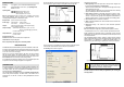
ELECTRICAL CONNECTIONS
The transmitter can be ordered as 4-20 mA current output or 0-10 Vdc voltage
output. The output signal is defined on purchase and cannot be later changed.
Figures 08 and 09 show the required electrical connections.
Figure 08 – 4-20 mA connections
Figure 09 – 0-10 Vdc connections
LOAD represents the output signal measurement equipment (controller, register, etc).
The connection wires go inside the transmitter through to the cable gland mounted
in the transmitter case.
INSTALLATION RECOMMENDATIONS
•
Conductors of small electrical signals must be distant from activation or high-
tension/current conductors, preferably passing through grounded conduits.
•
A specific electrical power supply network should be provided for instruments use
only.
•
In controlling and monitoring applications, possible consequences of any system
failure must be considered in advance.
•
RC filters (47 R and 100 nF, serial) in inductor charges (contactors, solenoids,
etc.) are recommended.
T E M P E R A T U R E T R A N S M I T T E R
T E M P - W M A N D T E M P - D M
O P E R A T I N G M A N U A L
WARRANTY
The manufacturer will grant to the owner of his equipment, duly identified through
the purchase invoice, a twelve-month warranty under the following terms:
1. The one year warranty begins on the day of shipment as stated on the sales bill.
2. During the warranty period all costs of material and labor will be free of charge
provided that the instrument does not show any evidence of misuse.
3. For maintenance, return the instrument with a copy of the sales bill to our factory.
All transportation and insurance costs should be covered by the owner of the
equipment.
4. Should any sign of electrical or mechanical shock, abuse, bad handling or
misuse be evident the warranty voids and maintenance costs will be charged.