MODEL:NF-HDMI-II Your excellent helper in cable test! INSTRUCTION MANUAL HDMI Cable Tester ORIGI NAL AUTHE NTIC Patented products, Counterfeiting not allowed REV1.
DESCRIPTION The Noyafa NF-HDMI-II HDMI Cable Tester is designed for professional HDMI installations. This portable device allows installers to quickly test, troubleshoot, and verify HDMI (high definition multimedia interface) cables.NF-HDMI is designed to test wire circuit state of HDMI cables with Type A & C connectors conforming to 1.0, 1.1, 1.2, 1.2a, 1.3, 1.3a, 1.3b, 1.3c, 1.4, 1.4a Category 1 and Category 2 cables.
● Do not use this tester with its case open, or with parts removed. Doing so may damage the tester and/or injure the user. ● Repairs and maintenance must only be carried out by qualified service personnel or qualified electricians/ technicians who know the dangers. ● Follow the recommendations of any Trade Organizations or Regulatory Agencies whose scope encompasses the use of this tester or injury to the user. ● Remove the battery when the tester not in use for longer than a month.
For HDMI cables Type A, C Test all HDMI cables with Type A to A, A to C and C to C connectors, especially for fragile, easily damaged HDMI patch cord and in-wall HDMI cables. Loopback function Design with loopback function allows test HDMI type A to A, A to C on main unit. 3 Test Modes ● Fast continuity scans for testing all conductors' status in a cable. ● Slow continuity scans for testing all conductors' status in a cable. ● Manual test for step by step scan detecting of individual conductors' situation.
SPECIFICATIONS: Cables Tested:HDMI cables with Type A & C connectors conforming to 1.0, 1.1, 1.2, 1.2a, 1.3, 1.3a, 1.3b, 1.3c, 1.4, 1.4a Category 1 and Category 2 cables. ● Support test (main unit and remote unit): 19 pin-to-pin wire map and shielding detection. ● Test interface of Master unit: HDMI (type A) ×1 pcs, Mini HDMI (type C) ×1 pcs. ● Test interface of Remote unit: HDMI (type A) ×1pcs, Mini HDMI (type C) ×1 pcs. ● Cable length:Under 50 meters.
PRODUCT DIAGRAM(Fig 1) 1.LOOPBACK:Mini-HDMI (C Type) This socket not only can be used on Master unit loopback test but also can be used on Master unit Mini-HDMI (C Type) with Remote unit Mini-HDMI (C Type) to perform scan test. 2.MAIN:HDMI (A Type) 3.LOOPBACK:HDMI (A Type) 4.Remote unit:HDMI (A Type) 5.Remote unit:Mini-HDMI (C Type) 6.Switch:MASTER/OFF/REMOTE 7.TEST:Automatic fast/slow scan or manual test for step by step. 8.Power and low battery indication. 9.HDMI (A Type) Pin number. 10.
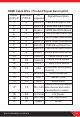
HDMI Cable Wire / Pin And Signal Description: Pin HDMI MINI-HDMI (A)Pin # (C)Pin # Assignment Signal Description 1 2 3 4 5 6 7 8 9 10 11 12 2 1 3 5 4 6 8 7 9 11 10 12 Clock - TMDS Clock Minus 13 14 CEC Consumer Electronics Control 14 15 16 17 15 16 Reserved Utility/Reserved SCL Serial Clock SDA Serial Data 17 13 18 19 S 18 19 S Your excellent helper in cable test! Data 2+ TMDS Red Data Plus Data 2S TMDS Red Data Shield Data 2- TMDS Red Data Minus Data 1+ TMDS Green Data Plus Data
Corresponding to the Pins Definition of the HDMI cables(Fig 2) 19 17 15 13 11 9 7 5 3 1 18 16 14 12 10 8 6 4 2 OPERATION Note ● When all LEDs are lighted all LEDs will decrease brightness. ● Master unit shorted pins LED will be brighter than others when shorted 2 pins above that is correct. ● Shield LED will light up after #1~19 LEDs light up in sequence on any testing mode. If the HDMI cable has a shield, the Shield LED will light up, if without shield the LED will be unlighted.
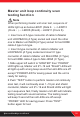
Master unit loop continuity scan testing function Note When performing master unit scan test, sequence of LEDs light up as below.LED#1 (Data 2﹢)→ LED#10 (Clock ﹢)→ LED#S (Shield)→ LED#11 (Clock S). ※ Insert one of A type connector of cable to Master unit LOOPBACK (A Type) socket and insert the other one to Master unit MAIN (A Type) socket for test HDMI cable A type to A type.
3. Master unit scan test result with beep sound as below. ● Straight: With a long “beep” sound: Meaning 1~19pin and S pin all straight connected. (Fig 3.) ● Open: with a short “beep” sound。No connected pins LED are off. Example: Test HDMI (A Type) to HDMI (A Type) cable that pin #2, #5, #8 and #11 are not connected , or test HDMI (A Type) to Mini-HDMI (C Type) cable that pin #1、#4、#7、#10 are not connected. (Fig 4.) ● Short: With three short “beep” sound. Shorted pins LED will light up at same time.
MASTER REMOTE MASTER C pin A pin C pin A pin C pin A pin C pin A pin Data 2+ Clock S Data 2+ Clock - Data 2S Clock - Data 2S CEC Data 2- CEC Data 2- Uti./Res. Data 1+ Uti./Res. Data 1+ Data 1S SCL Data 1S SCL SDA Data 1- SDA Data 1- DDC/CEC Data 0+ DDC/CEC Data 0+ +5V Power Data 0S +5V Power Data 0S Hot Plug Data 0- S Hot Plug S Shield S MASTER Data 0- S Shield Clock + Fig 3 . Straight REMOTE REMOTE Clock S Clock + Fig 4 .
Master unit with Remote unit automatic testing function ※ Insert one of A type connector of cable to Master unit MAIN (A Type) socket and insert the other one to Remote unit A Type connector for test HDMI cable A type to A type. ※ Insert A type connector to Master unit LOOPBACK (A Type) and insert C type connector to Remote unit Mini-HDMI (C Type) for test HDMI cable A type to Mini-HDMI (C Type).
● Open: Master unit and Remote unit both no connected pins LEDs are off. (Fig 8.) ● Short: Master unit testing short pin LEDs brighter than others. Remote unit shorted pins LEDs are off. (Fig 9.) ● Crossover: It can't be tested on this mode. Master unit with Remote unit slow continuity scan testing function: 1.Press “ TEST” button during LED indicate automatic testing result or Press twice “ TEST” button before LED off for perform automatic testing, it will continually scan #1~#19 pin and shield conductor.
● Short: Master unit LED brighter than others and Remote unit LED off when scan to shorted pins, Master unit and Remote unit both LED are all lighted up in sequence, Example : Test HDMI (A Type) to HDMI (A Type) cable that pin #4、#5、#6 are shorted, or teat HDMI (A Type) to Mini-HDMI (C Type) cable that pin #4、#5、#6 are shorted, or test Mini-HDMI (C Type) to Mini-HDMI (C Type) cable that pin #4、#5 、#6 are shorted. (Fig 9.
MASTER REMOTE C pin A pin C pin A pin Clock S Data 2+ Clock - Data 2S Clock S Data 2+ CEC Data 2- Clock - Data 2S A pin C pin A pin C pin Uti./Res. Data 1+ CEC Data 2- SCL Data 1S Uti./Res. Data 1+ Data 1S SDA Data 1- SCL DDC/CEC Data 0+ SDA Data 1- +5V Power Data 0S DDC/CEC Data 0+ Data 0- +5V Power Data 0S Hot Plug S S Shield Clock + Hot Plug S Data 0- S Shield Clock + Fig 7 .
MASTER REMOTE C pin A pin C pin A pin Clock S Data 2+ Clock - Data 2S Clock S Data 2+ CEC Data 2- Clock - Data 2S C pin A pin C pin A pin Uti./Res. Data 1+ CEC Data 2- SCL Data 1S Uti./Res. Data 1+ Data 1S SDA Data 1- SCL DDC/CEC Data 0+ SDA Data 1- +5V Power Data 0S DDC/CEC Data 0+ Data 0- +5V Power Data 0S Hot Plug S S Shield Clock + Hot Plug S Data 0- S Shield Clock + Fig 9 .
Master unit with Remote unit fast continuity scan testing function: 1.Press “ TEST” button during the slow continuity scan testing, or press three times“ TEST” button after the automatic testing LEDs are off:It will fast scan pin 1~19pin and Shield,Master unit and Remote unit both #1~19 and Shield LEDs will light up in sequence fast and sustained repeated automatic scan. 2.The test result please refer to the slow continuity scan testing function. (Fig 7. ~ Fig 10.
BATTERY LIFE AND REPLACEMENT: Caution To avoid unreliable test results, replace the battery as soon as the low battery indication appears. ● Warnings To avoid possible electric shock or personal injury, turn off the master unit and disconnect all test leads before replacing the battery. ● Battery Status:When ”POWER/LOW BATT.” LED is flashing on the master unit, it means the battery voltage is under 6.0V which couldn't power the device on. Please replace the battery as the following step: 1.
NF-306 NF-868 NF-8208 NF-268 NF-806R NF-816 NF-468L NF-3468 NF8108-M NF-388 NF-903 NF-906A Your excellent helper in cable test! 18
Your excellent helper in cable test! SHENZHEN NOYAFA ELECTRONIC CO.