SPECIFICATIONS Monitor Specifications MultiSync N9702 Monitor Notes Picture Tube Diagonal: Viewable: Image Size: Radius: 17 inch 16 inch 1210 mm 90° deflection, 0.26 mm dot pitch CRT, medium –short persistence phosphor, multi-layered anti static screen coating, semi-tint screen, Invar Shadow Mask and Opticlear screen surface. Input Signal ANALOG 0.7Vp-p/75 Ohms Separate sync.
CONTROLS – of the monitor + function as follows: On-screen display control buttons on the front SELECT RESET SELECT Enters and exits the OSM menu and decides the icon. CONTROL − / + Selects one of the controls and increases or decreases the adjustment. RESET Resets the highlighted control to the factory Setting. Adjusts the overall image and background screen brightness. Adjusts the image brightness in relation to the background. Red Color Control: Adjust the red contrast of the display.
demagnetized. Caution: Please allows a minimum of 20 minutes to elapse between uses of the Degauss Control. 9300K This color setting is adjusted at the factory to the stated Kelvin Moves the OSM menu vertically (up or down). Moves the OSM menu horizontally (left or right). EXIT: To exit the OSM window. Select EXIT in “ Icon select window” , then push SELECT button to exit OSM window. Note: If no buttons are pushed after 10 seconds while in OSM, the window will automactically disappear.
SERIAL NUMBER INFORMATION Refer to the serial number information shown below. SERIAL NUMBER LABEL MODEL SERIAL No. Manufactured Year : ( Last digit ) Manufactured Month : January to September October November December 1 to 9 X Y Z 00001 ~ on ward (Start from 00001 ~ when month is changed.) Factory mark : NPG CHINA ...............................
DISASSEMBLY Ÿ Ÿ Ÿ Ÿ Before you disassemble the set, turn off power and pull out the power plug. Use a proper screwdriver. If you user screwdriver that does not fit, you may damage the screws. Disassembly is the opposite process of assembly. Carefully discharge the CRT anode potential by grounding to CRT dag ground harness before removing Anode Cap. MAIN BOARD and CRT BOARD EXPLANATION 1. Disassemble a screw like a picture. 2.
ADJUSTMENT SPECIFICATIONS TABLE OF CONTENTS Page (1) Adjustment Tools ..................................................................................................................... 7 (2) Timing Table ........................................................................................................................... 7 (3) Definition for Normal Condition ................................................................................................. 7 (4) B+ Adjustment ........................
N9702 Adjustment Specifications (1) Adjustment tools: (A) (C) (E) (G) (I) (2) Color Analyzer Multi meter Convergence Meter Power Meter DDC test fixture (B) CHAROMA 2135 or Function Generator (D) Hi-Pot Probe (F) Degauss Probe (H) Automatic Alignment System TIMING TABLE(FACTORY MODE –16 MODES) MODE 1 2 3 4 5 6 7 8 9 10 11 12 13 (3) Ver. 1.
(5) H.V. Adjustment: (A) MODE: 86kHz 85Hz (B) PATTERN: ALL BLACK(Brightness cut off) (C) Adjustment: Adjust VR302 to make the high voltage has 25.5± 0.2KV (6) H-Free run Adjustment: (A) MODE: 30kHz (B) PATTERN: ALL WHITE (C) Adjustment: a. Tp6 connect 1uF/50V E-Cap to Ground. b. Adjust VR306 to take H o/p Frequency is 30kHz or the screen stand up. c. Take away E-Cap. (7) X-RAY test: (A) MODE: 86kHz 85Hz (B) PATTERN: CROSSHATCH(Brightness just cut off) (C) Test: a.
(12) FOCUS adjust: (A) (B) (C) (D) (E) (F) (G) MODE: 86k 1280*960(85) ALL WHITE Adjust H.parabola Vp-p by OSM H-Focus control to keep P303 pin1 300Vp-p MODE: 46.875kHz 800*600(75) ALL WHITE Adjust H.parabola Vp-p same (B) MODE: 69kHz 1024*768(85) PATTERN: CROSSHATCH Adjust Focus VR(S), horizontal line must be clearly. Adjust Focus VR(D), vertical line must be clearly. (13) Convergence adjust: (A) MODE: 69kHz 1024*768(85) (B) PATTERN: CROSSHATCH. (C) Adjustment: Use the convergence meter to check the spec.
(16) POWER SAVING Test: (A) MODE: 60kHz 1024*768(75) (B) PATTERN: ANY PATTERN. (C) Adjustment: a. It should be into suspend mode when signal quit after 5 sec.2nd the power output must be ≦15W. Check the LED color :Orange. b. It should be into power off mode when into suspend mode after 3sec.and the power output must be≦8W. Check the LED color :Orange c. Transfer the signal and check the screen is normal. Check the LED color :Green (17) DDC 1/2B Test: (A) MODE: Any MODE. (B) PATTERN: Any PATTERN.
(18) TIMING TABLE Preset Mode No. Signal Name Resolution Dot Clock (MH fh fv (kHz (Hz) Total 1 2 3 4 5 6 VGA 640*400 VGA 640*480 VESA 640*480 (75) VESA 640*480 (85) VESA 800*600 (75) (MAC) 832*624 (75) 800*600 49.500 46.875 832*624 57.283 49.725 640*400 640*480 25.175 25.175 31.47 31.469 640*480 640*480 31.500 36.000 37.50 43.269 70.09 59.940 75.00 85.008 75.00 74.550 (dot) (uS) 800 31.78 800 31.778 840 26.667 832 23.111 1056 21.333 1152 20.111 Disp (dot) (uS) 640 25.
Preset Mode No. Signal Name Resolution Dot Clock (MHz) fh (kHz) fv (Hz) 7 VESA 800*600 (85) 8 9 10 11 VESA VESA VESA VESA 1024*768 1280*1024 1024*768 1280*1024 (75) (60) (85) (75) 800*600 1024*768 1280*1024 1024*768 1280*1024 56.250 78.750 108.000 94.5 135.0 53.674 85.061 60.023 75.029 63.981 60.020 68.677 85 79.976 75.025 Total (dot) (uS) 1048 18.631 1312 16.660 1688 15.630 1376 14.561 1688 12.504 Disp (dot) (uS) 800 14.222 1024 13.003 1280 11.852 1024 10.836 1280 9.
15 16 FREE H.CENT Preset Mode No. Signal Name Resolution Dot Clock (MHz) fh (kHz) 640*400 1024*768 25.24 125.4 30.05 85.938 69.56 85.002 fv (Hz) Total (dot) (uS) 840 33.278 1728 11.636 Disp (dot) (uS) 640 25.357 1280 8.62 Front (dot) (uS) 16 0.631 64 0.431 Sync (dot) (uS) 64 2.536 160 1.077 Back (dot) (uS) 120 4.754 224 1.508 Total (H) (mS) 432 14.376 1011 11.764 Disp (H) (mS) 400 13.311 960 11.171 Front (H) (mS) 1 0.033 1 0.012 Sync (H) (mS) 2 0.067 3 0.
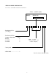
INSPECTION 1. Inspection of PLUG & PLAY communication 1-1. A construction of System This system should be connected as shown below. [ TEST PROGRAM PART No. 599910408 Program Disk Monitor Signal Generator PC R GB H V Power Cable Signal Cable Fixture Power Cable 1-2. Starting method 1) Input Signal Input signal must be separate sync. Timing is the signal whose vertical synchronization frequency is between 55Hz and 25kHz. Horizontal synchronization frequency should be set to 31.5kHz.
1-3. Operation ž The operation should be performed according to the screen message. ž The message of “ Normally Complete” means that writing of EDID data or PnP inspection completed normally. The message of “ Error” means that writing of EDID data or PnP inspection finished incorrectly. ž When the PnP inspection is completed, read EDID data would be displayed. And if the read EDID data differed from the original EDID data, the different bytes would be displayed in red.
1-5. EDID data file The EDID data file text is shown below. When you write or inspect EDID for this monitor, the following table can be used.
SAMSUNG CDT Spec. Screen and faceplate blemishes 1. Test procedure Set up the tube and adjust the light output on a blanked raster at the center of the screen for approximately 54 lm/m² (5 F/L) and 9300° K + 27 M.P.C.D. (OR 6550° K + 7 M.P.C.D.) color temperature. The screen should be viewed at a minimum distance of 60cm (2 feet). Ambient light level at the tube face should be approximately 1.0 lux.
4. Limits of phosphor screen blemishes (1) High-contrast blemishes The following criteria is applied to high-contrast blemishes. Allowable Minimum Separation(mm) Allowable No.
5. Limits of faceplate blemishes (1) Scratches The following criteria is applied to scratches on the faceplate of color display tubes. Maximum size of scratches allowable Width (mm) Length of single scratch(mm) Allowable number 0.05 or less 0.06 ~ 0.12 Ignore 50 or less 1 0.13 ~ 0.20 Over 0.20 10 or less 1 0 (2) Limits of faceplate defects The following criteria is applied to defects of useful screen on panel face.
LG CDT Spec. Limits of Screen and Faceplate Blemish 1. Test Procedure Set up the tube and adjust the light output on a blank raster at the center of the screen for approximately 15 FL and C.I.E x = 0.281, y = 0.311 (or x = 0.313, y = 0.329) color coordinate. The screen should be viewed at the minimum distance of 60 cm (2 feet). Ambient light level at the tube face should be approximately 5.0 Lux.
3.2 High contrast blemishes Blemish A B E Min. separation [mm] Zone A 1 0 Zone B 1 0 Total (zone A & B) 1 0 Zone A Zone B * (2) * (3) green 1 1 3 2 2 2 2 2 50 50 50 20 blue red Incase of C+D 5 5 4 4 10 50 20 50 20 1 trio * (1) C D Allowable number of blemishes 1 dot *Note: (1) 3 or more consecutive same color phosphor dots (2) 2 consecutive same color phosphor dots (3) 2 consecutive different color phosphor dots 3.
4. Faceplate blemishes The following criteria of the scratches and the limits of faceplate defects are applied to the useful screen of the panel face. 4.1 Scratches Width (mm) 0.05 or less 0.06 ~ 0.12 Length of single scratch (mm) Ignore 50 or less Allowable number 1 0.13 ~ 0.20 Over 0.21 6 or less 1 0 4.
4.3 Definition of coating defects Ring of defects Contents of defects Valuation of defect Ÿ Reflective spots and coating High-contrast The number of defects and quality area voids Ÿ Clearly visible by reflection Ÿ Cloudy visible by reflection Ÿ Same reflection as low contrast Ÿ Not include high contrast Low-contrast Elongated Ditto Ditto reflectance 4.4 Criteria of coating defects The following criteria is applied to defects of useful screen area.
TROUBLE SHOOTING Refer to User’ s Manual trouble shooting section before using this chart. TABLE OF CONTENTS Page 1. NO OPERATION, POWER LED FLASH ...................................................................................... 25 2. NO OPERATION, POWER LED OFF .......................................................................................... 26 3. VIDEO NOISE, UNSYNCHRONOUS .......................................................................................... 27 4. NO VIDEO .....
1.
2. NO OPERATION, POWER LED OFF POWER SW TURN OFF CHECK F101 CHECK Q101 1. 2. CHECK U101 U101 PIN6 PULSE O/P DC P/S O/P VOLTAGE SET AT 17V,CURRENT SET AT 200MA. POSITIVE CONNECT TO C109”+” . NEGATIVE CONNECT TO C105”-“ . SCOPE SET AT 10V/DIV, 10US/DIV, PROBE CONNECT TO Q101-GATE AND C105”-“ .
3.
4.
5. NO RASTER NO RASTER YES CHECK POWER SUPPLY NO B+ CHECK YES CHECK U301 PIN 1, PIN 2 H/V SYNC NO TROUBLE IN MCU U701 YES CHECK U701 PIN IS LOW NO YES CHECK U301 PIN 26, 3 H/V SYNC TROUBLE IN NO U301 YES CHECK T302 PIN 3 VOLTAGE 62V AT 31.
6. TROUBLE IN H. V SYNC TROUBLE IN HOR. OR VER. SYNC YES CHECK CONNECTOR S701 (PIN6,7), SIGNAL TROUBLE IN SIGNAL CABLE NO YES CHECK U701(PIN 13,15) H/V SYNC. SIGNAL TROUBLE IN NO H/V SYNC LINE & Q701, Q702 YES CHECK U701(PIN 16,17) H/V SYNC. SIGNAL NO CHECK U701(PIN 40) VOLTAGE 5V? NO TROUBLE IN 5V LINE YES YES YES CHECK U701 (PIN 18, 19) FREQ.8MHz CHECK U301(PIN 1, 2) NO TROUBLE IN H.
7.
8.
N9702 Theory of circuit operation This monitor contains the following blocks Page 1. Power Supply ............................................................................................................................ 34 2. Video Circuit & OSD ................................................................................................................... 34 3. Micro Controller System .............................................................................................................
1. Power Supply (a) The filter network consists of L104, C101, C107, L101, L102, C103 and C104. The main function of this filter circuit is to eliminate the noise that is produced from monitor itself. (b) T101 is an energy converter which transfers the energy from primary winding to secondary load. R104, C112 and D105 are the snubber circuit and they function to absorb the spike to protect Q101. (c) U101 is a pulse width modulation IC which supplies the drive pulse to Q101.
Mode State Input Output Sync User Factory Mode Sync H V H V ON Pulses Pulses Pulse Pulse Stand By No pulses Pulses L Factory PS CS 1 2 L H H L H L H 1 2 3 4 Depend on fH L L L L Suspend Pulses No pulses L L H L H L L L L PMS_OFF No pulses No pulses L L H L L L L L L ON Pulses Pulses L H H Stand By No pulses Pulses L L L H H L L L L Suspend Pulses No pulses L L L H H L L L L PMS_OFF No pulses No pulses L L L
(2) C344 is the Cs capacitor, and Q324 controls C345, Q326 controls C347, Q325 controls C346, Q327 controls C348. The U701 pin 1, 2, 3, 4 controls the Q324, Q326, Q325 and Q327 respectively. So different frequency has different combination to meet the requirement.
H V ADJ R,G,B R,G,B OSD/R,G,B,FB VF R,G,B X-RAY POTECT Q339,340 HOT T302 H-BLK Q273 R,G,B,/CUT OFF VIDEO PACK U203 OSD U202 RASTER CENTER Q313,314 DYNAMIC Q304, FOCUS Q305,303, Q302,338 H-O/P Q315 ABL Q272 VIDEO PRE-AMP U201 H-DRIVER Q316 76V,12V, 6.