INSTRUCTION MANUAL LISTED DIGITAL TIME SWITCH 24 HOUR DG180A DG280A DG280A-24 FOR TECHNICAL SUPPORT: 888.500.4598 A DIVISION OF NSi INDUSTRIES, LLC USA • 800.321.5847 • www.nsiindustries.
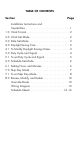
TABLE OF CONTENTS Section Page Installation Instructions and Capabilities . . . . . . . . . . . . . . . . . . . . . . . . . . . 1 1.0 Clock Format . . . . . . . . . . . . . . . . . . . . . . . . . . 2 2.0 Clock Set Mode . . . . . . . . . . . . . . . . . . . . . . . . 2 3.0 Date Set Mode . . . . . . . . . . . . . . . . . . . . . . . . 2 4.0 Daylight Saving Time . . . . . . . . . . . . . . . . . . . . 3 4.
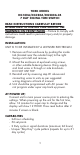
TORK MODEL DG180A/DG280A/DG280A-24 7 DAY DIGITAL TIME SWITCH READ INSTRUCTIONS CAREFULLY BEFORE ATTEMPTING TO INSTALL TIME SWITCH. SEE WARNING ON FRONT PANEL – Failure to comply with instructions could result in personal injury and/or property damage. INSTALLATION: UNIT IS TO BE INSTALLED BY A LICENSED ELECTRICIAN 1. Remove unit from enclosure by pushing the inside tab (located near the outside hasp) to the right. Swing unit to left and remove. 2.
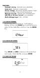
FEATURES Daylight saving - Automatic (user selectable) Leap year - Automatic compensation Power outage - Permanent schedule retention. Super capacitor provides 7 days of real time back up. Manual override - Until the next scheduled event AM/PM or 24 hour format - user selectable Multi-Voltage Input: 120 – 277VAC 1.0 CLOCK FORMAT The first time unit is powered up, it will display a flashing 12 Hour. Use HOUR key to set clock format to either 12 Hour (AM/PM) or 24 Hour. Press the ENTER key. 2.
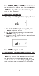
Press MONTH, DATE, and YEAR key to advance to the desired month, date and year, then press ENTER. NOTE: The day of the week will automatically set once the date is entered. 4.0 DAYLIGHT SAVING TIME After setting or modifying the date, display will show: a. For standard USA daylight savings (DSt), press MODE and go to step 5.0. b. For dates other than standard USA dates, press MONTH and go to step 4.1. c.
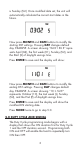
is Sunday (SU.) Once modified date set, the unit will automatically calculate the correct start dates in the future. Now press MONTH and DATE buttons to modify the starting DST settings. Pressing DAY changes default day. EXAMPLE: A screen showing “04:01 SU S” repre sents April (04), the first week (01), Sunday (SU), and the Start (S) of daylight savings time. Press ENTER to save and the display will show: Now press MONTH and DATE buttons to modify the ending DST settings. Pressing DAY changes default day.
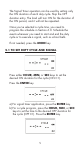
The Signal Timer operation can be used by setting only the ON duration of each duty cycle. Skip the OFF duration entry. The load will turn ON for the duration of the ON period, and it will not be repeated. Once you’ve selected a cycle time, you need to program the schedule in Section 6.0. Schedule the events whenever you need to start and end the duty cycle or to execute a signal, such as school bells. If not needed, press the MODE key 5.
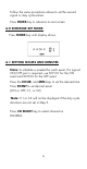
Follow the same procedures above to set the second signal or duty cycle entries. Press MODE key to advance to next screen. 6.0 SCHEDULE SET MODE Press MODE key until display shows: 6.1 SETTING HOURS AND MINUTES Note: A schedule is needed for each event. If a typical ON/OFF pair is required, use SCH 01 for the ON event and SCH 02 for the OFF event. Press the HOUR, and MIN keys to set the desired time.
Press ENTER to save. Follow the same procedures above to set more schedule entries. Press MODE when schedules are complete. 7.0 SKIP DAY MODE The Skip Day programming allows events to be repeated for a certain number of days, and then skipped for a number of days. Both active and skip periods are set by the user from 1 to 31 days. The timer will follow the programmed 24 hour schedule during each day of the active period.
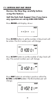
7.1 SETTING SKIP DAY MODE Review the Skip Day carefully before using this feature. Call the Tork Tech Support line if you have any question on set-up 888-500-4598. Press MODE until display shows: Press D/ON button to set the number of days load will be active. The first number pair will change. Press D/OFF button to set the number of days load will skip. The second number pair will change. Press DAY button to set today’s position within the D/ON and D/OFF pattern. The third number pair will change.
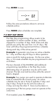
Example 1: The screen below shows a pattern with 3 active days and 2 skip days with today set as the first day of skip (01 OFF). Example 2: For the DG280A with opposite operations, screen below shows channel 2 set for a cycle with 2 active days and 3 skip days with today set as the first active day (01 ON) to be opposite the first example. Press MODE when Skip Days are complete. Unit is in the AUTO (automatic) mode. The word FLASH may appear to indicate a new program has been written to memory.
8.0 REVIEW, MODIFY AND DELETE Press MODE to advance to any of the following MODES: 1. AUTO MODE: In this automatic mode, the unit will execute the scheduled programs. Time, day, seconds and load status are displayed. C1or C2 is displayed when Duty Cycle is programmed and operating. OVERRIDE IN AUTO MODE: The load status of the channel can be manually changed by pressing the OVRD key (or OVR1 and OVR2 key for DG280A). The unit will stay in this position until the next scheduled event.
screen to show OFF. DST may be activated again by pressing DEL. Press ENTER to save changes. To change the from the standard DST month/week/day setting press HOUR and refer to step 4.1. 6. CYCLE MODE: To change duty cycle timing, press either the HOUR, MIN, or SEC keys. Press ENTER to save changes. 7. SCH MODE: To change schedule, press ENTER to advance to desired event. Press HOUR, MIN, EVENT to modify time settings. Press DEL to delete. Press ENTER after each modification to save changes. 8.
Now press ENTER briefly and everything in the timer memory is wiped off including real time, date and 12HOUR will flash. 4. A “PF” on the display indicates a Power Failure and the unit requires AC power to operate. The time and date are protected for 7 days by the super cap. The program is retained in permanent memory. 5. A “Lo” on the display indicates that the super cap has run low and the unit needs to be powered with AC. A minimum of 8 hours is required to fully charge the super cap. 6.
120/2 DG180A 120/277VAC 120/277VAC DG280A 120/277VAC DG280A-24 13
14
15
16
A DIVISION OF NSi INDUSTRIES, LLC USA • 800.321.5847 • www.nsiindustries.