INSTRUCTION MANUAL LISTED DIGITAL TIME SWITCH 7 DAY WITH INPUT DGU100A DGUM100A DGLC100A DGLC200A FOR TECHNICAL SUPPORT: 888.500.4598 A DIVISION OF NSi INDUSTRIES, LLC USA • 800.321.5847 • www.nsiindustries.
TABLE OF CONTENTS Section Page Installation Instructions and Capabilities . . . . . . . . . . . . . . . . . . . . . . . . . . . 1 0.0 Photo Sensor Calibration . . . . . . . . . . . . . . . . . . 2 1.0 Clock Format . . . . . . . . . . . . . . . . . . . . . . . . . 2 2.0 Clock Set Mode . . . . . . . . . . . . . . . . . . . . . . . . 2 3.0 Date Set Mode . . . . . . . . . . . . . . . . . . . . . . . . 3 4.0 Daylight Saving Time . . .
TORK MODEL DGU100A/DGUM100A/DGLC100A/DGLC200A 7 DAY DIGITAL TIME SWITCH WITH INPUT READ INSTRUCTIONS CAREFULLY BEFORE ATTEMPTING TO INSTALL TIME SWITCH. SEE WARNING ON FRONT PANEL – Failure to comply with instructions could result in personal injury and/or property damage. INSTALLATION: UNIT IS TO BE INSTALLED BY A LICENSED ELECTRICIAN 1. Remove unit from enclosure by pushing the inside tab (located near the outside hasp) to the right. Swing unit to left and remove. 2.
FEATURES Daylight saving - Automatic (user selectable) Leap year - Automatic compensation Power outage - Permanent schedule retention. Super capacitor provides 7 days of real time back up. Manual override - Until the next scheduled event AM/PM or 24 hour format - user selectable Multi-Voltage Input: 120 – 277VAC 0.0 PHOTO SENSOR CALIBRATION (IF EPC-A installed, per wiring at the back of the manual) a. Completely cover the EPC-A sensor. b.
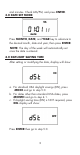
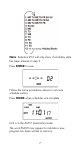
and minutes. Check AM/PM, and press ENTER. 3.0 DATE SET MODE Press MONTH, DATE, and YEAR key to advance to the desired month, date and year, then press ENTER. NOTE: The day of the week will automatically set once the date is entered. 4.0 DAYLIGHT SAVING TIME After setting or modifying the date, display will show: a. For standard USA daylight savings (DSt), press MODE and go to step 5.0. b. For dates other than standard USA dates, press MONTH and go to step 4.1. c.
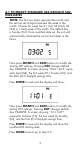
4.1 TO MODIFY STANDARD USA DAYLIGHT SAVINGS DATES NOTE: The first two digits represent the month and the second set of digits represent the week in the month. Choices for week are 01 (1st), 02 (2nd), 03 (3rd) or L (Last) week of the month. The default day is Sunday (SU.) Once modified date set, the unit will automatically calculate the correct start dates in the future. Now press MONTH and DATE buttons to modify the starting DST settings. Pressing DAY changes default day.
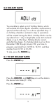
5.0 HOLIDAY DATES You are able to select up to 9 holiday blocks, which will exclude all of the regular schedules, and execute a special set that will only run on those specified days. If no holiday schedule is entered in step 6, operations will be omitted during the block. Holiday blocks can be anywhere from 1 day in length (the same start and end dates) or up to 364 days. Holiday blocks cannot end after they begin.
For a single day holiday, press the ENTER key (OR) Press the MONTH, and DATE keys to set the date to the desired end date (H1 OFF) Press the ENTER key. Repeat for all holidays. Press MODE when holidays are complete. 6.0 SCHEDULE SET MODE 6.1 SETTING HOURS, MINUTES, AND DAYS Note: A schedule is needed for each event. If a typical ON/OFF pair is required, use SCH 01 for the ON event and SCH 02 for the OFF event. Press the HOUR, and MIN keys to set the desired time.
Note: Selection #12 will only show if a holiday date has been entered in step 5. Press ENTER to save. Follow the same procedures above to set more schedule entries. Press MODE when schedules are complete. Unit is in the AUTO (automatic) mode. The word FLASH may appear to indicate a new program has been written to memory.
Press the EVENT key once (or twice for two circuit units) to activate current schedule then EVENT key again to return to AUTO mode. 7.0 REVIEW, MODIFY AND DELETE Press MODE to advance to any of the following MODES: 1. AUTO MODE: In this automatic mode, the unit will execute the scheduled programs. Time, day, seconds and load status are displayed. If today is a programmed holiday, the day of the week will flash.
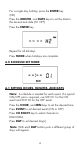
3. CLOCK MODE: Press HOUR and MIN to modify existing settings. Press ENTER to save changes. 4. DATE MODE: Press MONTH, DATE and YEAR to modify existing settings. Press ENTER to save changes. DAY is automatically adjusted. 5. DSt MODE: Factory default is set at US standard daylight savings dates noted by ON. To remove daylight savings time setting, press DEL to change screen to show OFF. DST may be activated again by pressing DEL. Press ENTER to save changes.
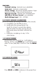
Now Press ENTER briefly and everything in the timer memory is cleared and 12HOUR will flash. 4. A “PF” on the display indicates a Power Failure and the unit requires AC power to operate. The time and date are protected for 7 days by the super cap. The program is retained in permanent memory. 5. A “Lo” on the display indicates that the super cap has run low and the unit needs to be powered with AC. A minimum of 8 hours is required to fully charge the super cap.
(For two channel units also set select switch to PHOTO setting.) 2. Sunset ON and Time OFF: Program an ON event at the earliest time you want to allow photo sensor to begin to operate. Then program a night time OFF event. (For two channel units also set select switch to PHOTO setting.) Example: ON at 3:00pm and OFF at 11:00pm MO – SU.
The other terminal block, TB2 is used as remote override inputs. Three wires are used: common wire, channel 2 (if DGLC200A), and channel 1. NOTE: Do not use any supply voltage for these wires. They should only be connected to dry (unpowered) switches. Closing contacts between the wires for channel 1 and common together will turn load 1 ON. Load will stay ON as long as the two wires are connected, no matter what the timer is set for, or the light level.
13
The Light Level dial adjusts the foot-candle (fc) set point for the control to turn ON. The load will be turned OFF and continue to hold OFF when the light level is twice this level or more. A timer program must be active for the light level feature to function see “Planning Your Program” below. The Time Delay dial adjusts the amount of time before the load turns ON or OFF due to light level change. The range is between 1 and 100 seconds.
15 is for timer function only SENSOR CALIBRATION SWITCH SENSOR CALIBRATION LED Two channel front panel controls are use if photo sensor EPC-A (included with DGLC200A) is connected. Each channel has a switch to set its independent control logic. The up position (PHOTO) is timer/light level logic. The down position (TIMER) is timer logic and ignores the photo sensor.
DGU100A/DGLC100A DGU100A/DGLC100A DGU100A/DGLC100A DGU100A/DGLC100A 120/277VAC 120/277VAC 120/277VAC 120/277VAC DGUM100A DGUM100A DGUM100A DGUM100A 120/277VAC 120/277VAC 120/277VAC 120/277VAC DGLC200A DGLC200A DGLC200A DGLC200A 120/277VAC 120/277VAC 120/277VAC 120/277VAC 16
17
18
19
20
A DIVISION OF NSi INDUSTRIES, LLC USA • 800.321.5847 • www.nsiindustries.