NU-METRICS® A QUIXOTE COMPANY UNION TOWN, PA 15401 Traffic Recording nu-metrics’ A QUIXOTE COMPANY SEPTEMBER 2003 OPERATIONAL MANUAL: HARDWARE Prepared by the: Engineering Department Nu-Metrics, Inc. Authorized for Distributors, Administrator and Installers Only Other requests for this document shall be referred to Nu-Metrics, Inc.
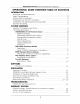
Operational Overview for Permanent Count Stations OPERATIONAL GUIDE OVERVIEW TABLE OF CONTENTS INTRODUCTION Disclaimer and Guide Objective Lo... Safety Considerations Le System Safety Precautions . ee Compliance with FCC Part 15 Class A Compliance with National Electrical Code (NEC) . Electrical Grounding . . «Le SYSTEM OVERVIEW Glossary of Frequently Used Terms... iru.
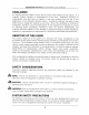
Operational Overview for Permanent Count Stations DISCLAIMER An attempt has been made to insure the accuracy of the material in this manual. (tis supplied without warranty or representation of any kind. Nu-Metrics assumes no responsibility and shall have no liability of any kind arising from the use of this publication or the material contained herein. Nu-Metrics reserves the right to add, delete and/or change the material at any time.
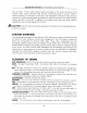
Operational Overview for Permanent Count Stations A caution: Never replace or substitute systems components with third party devices. Only replace components with Nu-Metrics authorized equipment. DO WARNING: The electrical power connection must be installed by a certified electrician because of the potential for electrical shock. OH WARNING: Avoid power tines! Use extreme caution when performing overhead work. Contact with power lines or other circuits could cause serious injury.
Operational Overview for Permanent Count Stations 810 and 820. These codes require proper grounding of the metal structure of the outdoor tower, tripod, antenna mast and any connecting cable at a point where it enters a building. At the point of entrance, the installation contractor must provide a connection to the nearest properly grounded rod, steel structures or any other metallic surface per NEC Article 250.
Operational Overview for Permanent Count Stations RF — Radio Frequency RFM Radio Frequency Module, the device that gathers and decodes Groundhog messages, stores them to local memory. SPREAD SPECTRUM Radio transmission method that spreads the signal over a wide bandwidth. VMI Vehicle Magnetic Imaging, a method of using a very small magnetic sensor to measure the magnetic disturbance of a vehicle passage through the earth's magnetic field.
Operational Overview for Permanent Count Stations The G-4 traffic analyzer employs Spread Spectrum Radio Frequency (RF) data transfer technology in the 808-922 MHz frequency range. Spread Spectrum Technology allows multiple Groundhogs to transmit simultaneously without interference. When a Groundhog transmits stored data, it sends three redundant data packets to the RFM. MAGNETIC SENSING Magnetic sensing used by the Groundhog detects disturbances in the Earth’s magnetic field.
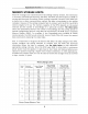
Operational Overview for Permanent Count Stations LENGTH CLASSIFICATION The Groundhog measures vehicle length and transmits this information to the RFM every period. Length classification is based on vehicle length and stored in bins similar to the speed classification. The length bins are used to group vehicles into six predefined length ranges. For example, length bin one stores the number of vehicles that are measured by the Groundhog between O and 20 feet long.
Operational Overview for Permanent Count Stations microprocessor to handle the complexity associated with direct sequence decoding. Upon receipt of valid data from transmitting Groundhogs, the information is stored and transmitted to the ultimate destination (traffic headquarters, extended memory module, etc.).
Operational Overview for Permanent Count Stations MEMORY STORAGE LIMITS When RF messages are transmitted from Groundhog roadway sensors, the information is received, processed and stored by the RFM. The RFM uses 64 kilobytes of RAM for storing data from each Groundhog. When a polling computer connects to the RFM from a phone line or other communication method, the data is downloaded to the polling computer. However, if the polling computer fails to connect with the RFM, the FM's memory begins to fill up.
Operational Overview for Permanent Count Stations SOFTWARE This page covers the installation of the Wireless Data Management (WDM) software designed to collect, store and display information from the PCS System. The PCS system software is comprised of several modules, each providing a different function. Each module performs a unique task and functions independently. THE MODULES INCLUDED ARE: Communication Module: An application that communicates to the Count Station equipment, collecting and storing data.
Troubleshooting Guide for the Permanent Count Stations TROUBLESHOOTING PERMANENT COUNT STATION Tools Required: LJ Analog telephone 1 Voltmeter THIS CHECKLIST APPLIES TO A SITE POWERED BY AC POWER! 1. CHECK POWER STATUS OF THE CABINET A Verify the site has AC electrical power, 0 Verify the circuit break has not tripped. 0 Reset the circuit breaker, switch OFF then back ON. 0 Check the green status LED is ON for the surge arrest or (the surge arrest or has a right yellow front with an LED in the center).
Limited Warranty Section for Permanent Count Stations LIMITED WARRANTY GENERAL COVERAGE: This Nu-Metrics system, but not items or computer products covered by other manufacturers warranty, is warranted to the owner for a period of one year from the date of original purchase against defects in manufacture or workmanship. This limited warranty is given by Nu-Metrics and not by the distributor or representative from whom the equipment was purchased.
Warranty and Service for Permanent Count Stations LIMITED WARRANTY ON MEDIA: Nu-Metrics warrants the disks on which the software is recorded to be free from defects in materials and faulty workmanship under normal use for a period of ninety (20) days from the date of delivery as evidenced by a copy of the sales invoice.
Installation Procedure for the Groundhog® G-4 Permanent Traffic Analyzer SELECTING A LOCATION oH WARNING! 1. Select locations for installing Groundhogs that do not interfere with embedded loops, underground cable, conduit, pipes or other obstructions. 2. Close the selected traffic lane after checking appropriate state and local ordinances for proper procedures and requirements. States often require acceptance of an approved Maintenance and Protection of Traffic (MPT) plan before closing a traffic lane.
Installation Procedure for the Groundhog® G-4 Permanent Traffic Analyzer INSTALLATION OF THE GROUNDHOG SENSOR Installing the Groundhog is a very simple process when compared to many of the industry alternatives. However, there are a few important tips to remember during installation. J Ensure that line of site exists between the sensor & the local base unit (see p12). 1 Be knowledgeable about the surface to be drilled. Concrete is considerably harder A to drill through.
installation Procedure for the Groundhog® G-4 Permanent Traffic Analyzer The following hardware is needed for a PCS installation. PRACTICE ALL ROUTINE SAFETY PROCEDURES FOR INSTALLATIONS. GROUNDHOG SENSOR INSTALLATION: {1 Core drill machine (i.e. Milwaukee Mandrill, Amps ~ 20, Volts 120 US) J Water and water valve attachment for the wet core drill system Ld Core drill bit in ONE of the following diameters: Id WITH weather option €.75 inches I. WITHOUT weather option 6.
Installation Procedure for the Groundhog® G-4 Permanent Traffic Analyzer BEGINNING INSTALLATION. STEP 14. Locate the center of the traffic lane CHECKLIST! Verify that you have all of the and mark the road with pat. This will be the equipment needed for the Nu-Metrics' Groundhog location {center of lane marking) of the installation, Groundhog canister. = al I STEP 3 Place the core drill aver the center of STEP 2 Mark the drill bit to a depth of the lane mark and prepare to drill.
Installation Procedure for the Groundhog? G-4 Permanent Traffic Analyzer IMPORTANT: Make sure the work area is clean a minimum of 2 feet around the hols. Remove all A debris using a broom, wet/dry vacuum, hose, or other method. Once the surrounding area is clean and dry, you may proceed. STEP 6 Since there Is water in and around the work area, you will need to use a propane torch to dry the area to proceed.