
Installation Guide


INSTALLATION INSTRUCTIONS
READ & SAVE THESE INSTRUCTIONS!
Installation from Below
Riser Installation
2
1
/2" DIA. HOLE
THROUGH SOLE PLATE
2
1
/2" DIA. HOLE
THROUGH HEADER PLATE
1
13
/16"
1
13
/16"
1
13
/16"
1
13
/16"
1
13
/16"
6" TO ALLOW FOR
FINAL CONNECTION
HEADER
ADDITIONAL 2-CONDUCTOR
CABLE – MODEL 376
ADDITIONAL TUBING
MODEL 380
MODEL 388
STOP COUPLING
MODEL 395 – INLET
ROUGH-IN ASSEMBLY
18" MAX.
18" MAX.
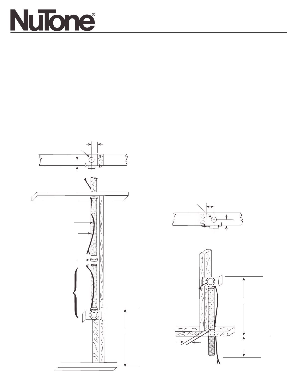
1. Drill a 2
1
⁄2" diameter hole in sole plate in line with
opening of inlet bracket fitting. Refer to Figure 1 below,
for center line dimensions.
2. Refer to Figure 2. If tubing is to be installed as part of a
riser line, add one Model 388 Stop Coupling and
enough 2" vacuum tubing to extend through header.
3. Be sure to attach additional 2-conductor, low voltage
cable (Model 376) on all riser installations.
4. Install cover plate provided.
Central Cleaning System
Rough-In Assembly
MODEL: 395
FIGURE 2 FIGURE 1