
Instructions / Assembly


Page 3
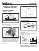
MODEL 744LEDNT
HORIZONTAL POWER
CABLE CONNECTION
VERTICAL
POWER CABLE
CONNECTION
WIRING PLATE
WHITE
TO
WHITE
BLUE (FAN)
TO
BLACK
TOP / BACK
OF HOUSING
3-WIRE PLUS
GROUND
POWER
CABLE
GROUND TO
WIRING PLATE
Fan operated with separate on/off switch,
speed control or timer.
Light operated with separate on/off switch.
FLUSH
3. Pound in nails.
Remove unit temporarily, and pound nails partially into joists at
all four marked locations.
4. Hang and secure housing.
Hang unit from nails. Check to make sure that there will be a 1/8”
gap between bottom of housing and ceiling material. Pound nails
tight. For wide joist centers: A #8 x 3/8 self-tapping screw can be
used to join extended brackets together and create a rigid mount.
To ensure a noise-free mount, crimp the bracket channels tightly
around mounting brackets.
5. Attach damper/duct connector.
Snap the damper/duct connector onto housing. Make sure that
tabs on the connector lock in housing slots. (Top of damper/duct
connector will be flush with top of housing.) Install ductwork.
6. Choose power cable direction.
Remove wiring plate. When re-attached, the wiring plate allows
the power cable to enter unit horizontally or vertically.
7. Connect wiring.
Unit can be wired from outside of housing as shown. Use UL
approved connectors to wire per local codes.
Fan and Light operated with single on/off switch
BLACK (LAMP)
TO RED
WIRING PLATE
WHITE
TO
WHITE
BLUE AND
BLACK
TO BLACK
TOP / BACK
OF HOUSING
2-WIRE PLUS
GROUND
POWER
CABLE
GROUND TO
WIRING PLATE