
Ventilation Fan with Fluorescent Light Installation Instructions
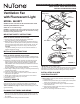


READ & SAVE THESE INSTRUCTIONS!
INSTALLATION INSTRUCTIONS
Ventilation Fan
with Fluorescent Light
Suitable for use in insulated ceilings.
WARNING: To reduce the risk of fire or electrical shock, do not use this
fan with any solid-state speed control device. Do not install in a ceiling
insulated to a value greater than R-40.
IMPORTANT SAFETY INSTRUCTIONS
WARNING – TO REDUCE THE RISK OF FIRE, ELECTRIC SHOCK, OR
INJURY TO PERSONS, OBSERVE THE FOLLOWING:
A. Use this unit only in the manner intended by the manufacturer.
If you have questions, contact the manufacturer.
B. Before servicing or cleaning unit, switch power off at Service Panel and
lock Service Panel to prevent power from being switched on accidentally.
When the service disconnecting means cannot be locked, securely fas-
ten a prominent warning device, such as a tag, to the service panel.
CAUTION:
For general ventilating use only. Do not use to exhaust hazardous or
explosive materials and vapors.
INSTALLATION INSTRUCTIONS
WARNING – TO REDUCE THE RISK OF FIRE, ELECTRIC SHOCK, OR
INJURY TO PERSONS, OBSERVE THE FOLLOWING:
A. Installation work and electrical wiring must be done by qualified person(s)
in accordance with all applicable codes and standards, including fire-rated
construction.
B. Sufficient air is needed for proper combustion and exhausting of gases
through the flue (chimney) of fuel burning equipment to prevent back
drafting. Follow the heating equipment manufacturer’s guideline and
safety standards such as those published by the National Fire Protection
Association (NFPA),
and the American Society for Heating, Refrigeration and Air Conditioning
Engineers (ASHRAE), and the local code authorities.
C. When cutting or drilling into wall or ceiling, do not damage electrical wiring
and other hidden utilities.
D. Ducted fans must always be vented to the outdoors.
E. If this unit is to be installed over a tub or shower, it must be marked as
appropriate for the application.
F. NEVER place a switch where it can be reached from a tub or shower.
G.
For installation in sloped ceilings up to 12/12 pitch.
H.
Ductwork must point up.
FOR BEST RESULTS
When installing the Exhaust Fan/Light in a new construction site, install
housing during the rough-in construction of the building. The blower unit,
reflector and grille should be installed after the finished ceiling is in place.
Refer to instructions on page 3 to install the Exhaust Fan/Light in an exist-
ing finished building.
PLANNING DUCTWORK AND WIRING
1. Use 4” round duct.
2. Plan duct run from discharge opening of fan to the outside. For best fan
performance, make duct run as short as possible and use minimum num-
ber of elbows.
3. Use optional NuTone ducting accessories as needed.
MODEL: 8663RFT
Suitable for use in shower or tub enclosure when used
with GFI protected branch circuit.
IMPORTANT: Use wire suitable for 90°C.
Plan to run 120vAC house wiring (with ground) from power source, through
wall switches, to junction box in fan. For separate control of fan and light, two
wall switches are required. See NuTone Catalog for accessory switches.
INSTALLATION IN A NEW
CONSTRUCTION SITE
PREPARATION
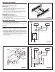
1. Refer to Figure 1. Remove power unit/blower assembly from housing.
A. Unplug power unit.
B. Remove screw (located next to plug-in receptacle) which holds power/
blower unit mounting plate in place. Save screw.
C. Lift mounting plate at end near the plug-in receptacle until blower
wheel clears the scroll.
D. Remove plate by pulling its tabs out of slots in housing. Set power/
blower unit aside until needed.
2. Remove one of the wiring knockouts from housing.
Wiring
Knockouts
FIGURE 1
Housing
Scroll
Slots
Power/Blower
Unit
Reflector
Assembly
Acorn Nut
Grille/Lens
Assembly
Mounting
Springs (2)
Duct
Collar
Tabs
TO REGISTER THIS PRODUCT, VISIT WWW.NUTONE.COM
Hanger Bars