WWW.BROAN-NUTONE.COM WWW.NUTONE.
Safety . . . . . . . . . . . . . . . . . . . . . . . . . . . . . . . . . 3-4 Operation . . . . . . . . . . . . . . . . . . . . . . . . . . . . . . . 5 Cleaning and Maintenance . . . . . . . . . . . . . . . . . 6 Motor Grease Filters Non-Ducted Recirculation Filters Fan Blade Stainless Steel Cleaning Painted Finish Cleaning Installation . . . . . . . . . . . . . . . . . . . . . . . . . . . . 7-19 INSTALLATION MANUAL TABLE OF CONTENTS Recommended Tools and Accessories for Installation . . . . . . . . . .
READ AND SAVE THESE INSTRUCTIONS ! Intended for domestic cooking only ! INSTALLER: LEAVE THIS MANUAL WITH HOMEOWNER. In U.S.A., register your range hood online at www.broan-nutone.com In Canada, register your range hood online at www.nutone.ca ! WARNING TO REDUCE THE RISK OF FIRE, ELECTRIC SHOCK, OR INJURY TO PERSONS, OBSERVE THE FOLLOWING: • Use this unit only in the manner intended by the manufacturer.
! WARNING TO REDUCE THE RISK OF A RANGE TOP GREASE FIRE: a) Never leave surface units unattended at high settings. Boilovers cause smoking and greasy spillovers that may ignite. Heat oils slowly on low or medium settings. b) Always turn hood ON when cooking at high heat or when flambeing food (i.e.: Crêpes Suzette, Cherries Jubilee, Peppercorn Beef Flambé). c) Clean ventilating fan frequently. Grease should not be allowed to accumulate on fan, filters or in exhaust ducts. d) Use proper pan size.
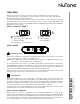
Operation Always turn your hood on before you begin cooking to establish an air flow in the kitchen. Let the blower run for a few minutes to clear the air after you turn off the range. This will help keep the whole kitchen cleaner and fresher.
Cleaning and Maintenance Proper maintenance of the Range Hood will assure proper performance of the unit. MOTOR The motor is permanently lubricated and never needs oiling. If the motor bearings make excessive or unusual noise, replace the motor with the exact service motor. The fan blade should also be replaced. GREASE FILTERS The grease filters should be cleaned frequently. Use a warm dishwashing detergent solution. Grease filters are dishwasher safe.
For ADA compliance installation guidelines, please type the model number into our website. Recommended Tools and Accessories for Installation • • • • • • • • • • • • • • • Measuring tape Phillips screwdriver no.
Contents Before proceeding to the installation, check the contents of the box. If items are missing or damaged, contact the manufacturer.
Prepare the Hood NOTE: Since this manual covers many range hood models, some details in the following illustrations may sligthly differ from your unit. 1 ] If present, remove all protective polyfilm from the hood and/or parts. 2 ] Using the finger cup (AVDF1, AVSF1-2 Series) or the tab (AVSF1 Series), remove the grease filters from the hood by pushing down and tilting filters out . B C 3 ] Remove the EZ1 brackets from inside the hood by cutting off the tie wrap.
5 ] Remove 7” Round Duct Plate from top/back of hood (see illustration below). Keep the screws for further use. 7” ROUND DUCT PLATE 2 SCREWS 6 ] Remove Electrical Power Cable Knockout from top (vertical exhaust) or back (horizontal exhaust) of hood. Install an appropriate strain relief, 1/2” diameter (not included). ELECTRICAL POWER CABLE KNOCKOUT NON-DUCTED INSTALLATION ONLY 7 ] Remove 3 screws retaining the recirculation cover plate (shaded part in illustration below) to the hood.
DUCTED INSTALLATION ONLY 8 ] Remove 3¼” x 10” vertical, 3¼” x 10” horizontal, or 7-inch round knockout plate as appropriate for your ducting method (see FIGURES 1 A and 1 B).
Prepare the Hood Location NOTE: Before starting installation, read all the steps of these instructions. Use the illustration below to identify your kitchen cabinet type. FRAMED CABINET FRAMELESS CABINET This manual covers 2 kinds of installation: the standard (without EZ1 brackets) and the EZ1 one-person installation system (using included template and brackets). For the standard installation, go to page 17.
4 ] Drill a 1/8” dia. pilot hole for house wiring, at A location on template. 5 ] Use a sharp pencil or 1/8” drill bit to mark the locations for the appropriate duct access holes (16 locations for 7” round duct, or 4 corner locations for rectangular duct). Remove the template. 6 ] Draw the border for the exhaust ducting by linking its marks (16 for round duct and 4 for rectangular duct), then cut the opening in the cabinet bottom (vertical exhaust) or in the wall (horizontal exhaust).
FRAMELESS CABINET Refer to the marking on brackets to determine the correct installation side and orientation. X Y Z 3X [ \ INSTALLATION MANUAL INSTALLATION 7/64” 14 Align the corresponding bracket to the cabinet side, while placing rear end of bracket against the wall. Draw a line on the outer edge of the bracket (as shown). Slide the bracket towards the center of cabinet and align the outside edge of the bracket with the marked line, keeping the rear end edge leaning on the wall.
Install the Hood (EZ1 Bracket) NOTE: The following procedure applies to both framed or frameless cabinet installations. 1 ] Run house power cable between service panel and hood location. 2 ] There are 2 pairs of recessed holes on each side of the top of the hood (on rear: A and B, on front C and D on illustration below); these holes allow the range hood to hang on the brackets (previously installed).
7 ] For framed cabinet, secure the hood to the EZ1 brackets using 4 no. 8-18 x 1/2” metal screws (included in parts bag). Insert 2 screws per side, in the slots (as shown in insets on illustration below). 8 ] For frameless cabinet, secure the hood to the cabinet using 4 no. 8 x 5/8” round head wood screws (included in parts bag). Insert 2 screws in the slots (as shown in insets on illustration below).
Standard Installation (without EZ1 brackets) 1 ] Use the proper diagram below for placement of ductwork and electrical cutout in cabinet or wall. For a non-ducted installation, DO NOT cut a duct access hole, only cut the hole for electrical wiring.
Install the Hood (Standard Installation) 1 ] Run house power cable between service panel and hood location. Run the house power cable into the hood through the strain relief previously installed in step 6 on page 10. 2 ] Hang hood from (4) mounting screws previously installed. Slide hood back towards wall until mounting screw heads are engaged in narrow end of keyhole slots in top of hood. Tighten screws securely. Attach power cable to the hood using the strain relief.
Connect the Wiring ! WARNING Risk of electric shock. Electrical wiring must be done by qualified personnel in accordance with all applicable codes and standards. Before connecting wires, switch power off at service panel and lock service disconnecting means to prevent power from being switched on accidentally. MOTOR GROUND WIRE GROUND SCREW HOUSE POWER CABLE 1 ] Connect House Power Cable to range hood wiring: BLACK to BLACK, WHITE to WHITE and GREEN or bare wire under GREEN ground screw.
AVSF1 AND AVSF1-2 SERIES COLOR CODE BK BL BN BN/W BLACK BLUE BROWN BROWN/WHITE G/Y O R W GREEN/YELLOW ORANGE RED WHITE LED Light Switch BL BK W 2 1 LED driver R input output BK R BK 1 2 W LED W BK BK Motor Switch FAN MOTOR 6 5 4 3 2 1 120 V AC R (Low) BK (High) Line W W Neutral R O BK G/Y W BN/W G/Y Ground BN AVDF1 SERIES 1 2 3 4 5 6 COLOR CODE BK BL BN BN/W J6 Override BLACK BLUE BROWN BROWN/WHITE G/Y O R W GREEN/YELLOW ORANGE RED WHITE LED J4 J10 Interface 8 7 6 5 W R L
AVSF1 SERIES (30 IN. WIDTH) KEY NO. 1 2 3 4 5 6 7 8 * * * * ITEM NOT SHOWN. REPLACEMENT PARTS AND REPAIRS In order to ensure your unit remains in good working condition, you must use Broan-NuTone LLC or Venmar Ventilation ULC genuine replacement parts only. Broan-NuTone LLC or Venmar Ventilation ULC genuine replacement parts are specially designed for each unit and are manufactured to comply with all the applicable certification standards and maintain a high standard of safety.
AVSF1 SERIES (36 IN. WIDTH) QUANTITY 36" 36" 36" 36" BLACK WHITE STAINLESS BLACK STAINLESS S97020029 RECIRCULATION COVER PLATE, BLACK (INCLUDING SCREWS) 1 S97020030 RECIRCULATION COVER PLATE, WHITE (INCLUDING SCREWS) 1 1 S97020031 RECIRCULATION COVER PLATE, STAINLESS STEEL (INCL. SCREWS) 1 S98011873 RECIRCULATION COVER PLATE, BLACK STAINLESS (INCL.
AVDF1 SERIES KEY NO. * * * * ITEM NOT SHOWN. REPLACEMENT PARTS AND REPAIRS In order to ensure your unit remains in good working condition, you must use Broan-NuTone LLC or Venmar Ventilation ULC genuine replacement parts only. Broan-NuTone LLC or Venmar Ventilation ULC genuine replacement parts are specially designed for each unit and are manufactured to comply with all the applicable certification standards and maintain a high standard of safety.
AVSF1-2 SERIES KEY NO. 1 2 3 4 5 6 7 INSTALLATION MANUAL SERVICE PARTS 8 24 9 10 * * * * * * QUANTITY 30" 30" BLACK STAINLESS STAINLESS S97020031 RECIRCULATION COVER PLATE, STAINLESS STEEL (INCL. SCREWS) 1 S98011873 RECIRCULATION COVER PLATE, BLACK STAINLESS (INCL.
INSTALLATION MANUAL WARRANTY Limited Warranty Warranty Period and Exclusions: Broan-NuTone LLC and Venmar Ventilation ULC (either being the “Company”) warrants to the original consumer purchaser of its product (“you”) that the product (the “Product”) will be free from material defects in the Product or its workmanship for a period of one (1) year from the date of original purchase (or such longer period as may be required by applicable law).
WWW.BROAN-NUTONE.COM WWW.NUTONE.
Sécurité . . . . . . . . . . . . . . . . . . . . . . . . . . . . . . . 3-4 Fonctionnement . . . . . . . . . . . . . . . . . . . . . . . . . . 5 Nettoyage et entretien . . . . . . . . . . . . . . . . . . . . . 6 Moteur Filtres à graisses Filtres de recirculation Hélice Nettoyage de l’acier inoxydable Nettoyage des surfaces peintes Installation . . . . . . . . . . . . . . . . . . . . . . . . . . . . 7-19 MANUEL D’INSTALLATION TABLE DES MATIÈRES Outils et accessoires recommandés pour l’installation . . . .
VEUILLEZ LIRE ET CONSERVER CES DIRECTIVES ! Conçues pour usage domestique seulement ! INSTALLATEUR : LAISSER CE MANUEL AU PROPRIÉTAIRE. Aux États-Unis, enregistrez votre hotte en ligne à www.broan-nutone.com Au Canada, enregistrez votre hotte en ligne à www.nutone.ca ! AVERTISSEMENT AFIN DE RÉDUIRE LES RISQUES D’INCENDIE, D’ÉLECTROCUTION OU DE BLESSURES CORPORELLES, SUIVEZ LES DIRECTIVES SUIVANTES : • N’utilisez cet appareil que de la façon prévue par le manufacturier.
! AVERTISSEMENT AFIN DE RÉDUIRE LES RISQUES DE FEU DE CUISINIÈRE : a) b) c) d) Ne jamais laisser les appareils de cuisson sans surveillance lorsqu’ils sont réglés à feu vif. Les débordements engendrent de la fumée et des déversements graisseux pouvant s’enflammer. Chauffez l’huile lentement, à feu doux ou moyen. Mettez toujours la hotte en marche lorsque vous cuisinez à feu vif ou que vous cuisinez des mets flambés (par ex. : crêpes Suzette, cerises jubilé, steaks au poivre flambés).
Fonctionnement Toujours mettre en marche la hotte avant de commencer la cuisson afin d’établir une circulation d’air dans la cuisine. Laisser également la hotte fonctionner quelques minutes après l’arrêt de la cuisinière afin de nettoyer l’air. Cela aidera à maintenir la cuisine plus propre et plus fraîche. Ces hottes sont munies de modules DEL offrant un éclairage brillant, issus de la plus récente technologie en matière d’éclairage de surface de cuisson.
Nettoyage et entretien L’entretien adéquat de la hotte préservera ses performances. MOTEUR Le moteur est lubrifié en permanence et n’a pas besoin d’être huilé. Si les roulements du moteur sont anormalement bruyants, remplacer le moteur uniquement par le même modèle. L’hélice doit aussi être remplacée. FILTRES À GRAISSES Les filtres à graisses doivent être nettoyés fréquemment. Utiliser une solution d’eau chaude et de détergent. Les filtres sont lavables au lave-vaisselle.
Pour connaître les lignes directrices de l’ADA (Americans with Disabilities Act) concernant l’installation, veuillez entrer votre numéro de modèle dans notre site Internet.
Contenu Avant de procéder à l’installation, vérifier le contenu de la boîte. Si des articles sont manquants ou endommagés, contacter le manufacturier.
Préparation de la hotte NOTE : Puisque ce manuel couvre plusieurs modèles de hottes de cuisinière, certains détails de votre hotte peuvent être légèrement différents de ceux illustrés. 1 ] Retirer toute présence de pellicule de plastique protectrice sur la hotte et/ou ses pièces.
5 ] Retirer la plaque pour conduit rond de 7 po du dessus de la hotte (voir l’illustration ci-dessous). Garder les vis pour usage ultérieur. PLAQUE POUR CONDUIT ROND DE 7 PO 2 VIS 6 ] Retirer l’ouverture préamorcée du câble d’alimentation électrique du dessus (évacuation verticale) ou de l’arrière de la hotte (évacuation horizontale). Installer un serre-fils approprié de 1/2 po de diamètre (non inclus).
INSTALLATION AVEC CONDUITS SEULEMENT 8 ] Retirer les ouvertures préamorcées de 3¼ po x 10 po verticale, 3¼ po x 10 po horizontale, ou 7 po ronde selon le mode d’évacuation choisi (voir les FIGURES 1 A et 1 B).
Préparation de l’emplacement de la hotte NOTE : Avant de commencer l’installation, veuillez lire toutes les étapes de cette instruction. Identifier votre type d’armoire de cuisine à l’aide de l’illustration ci-dessous. ARMOIRE À FOND EN RETRAIT ARMOIRE À FOND ÉGAL Ce manuel couvre deux types d’installation : l’installation standard (sans les supports EZ1) et le système d’installation par une personne EZ1 (en utilisant le gabarit et les supports inclus). Pour l’installation standard, allez en page 17.
4 ] Percer un avant-trou de 1/8 po de diamètre pour le câble d’alimentation, à l’emplacement A sur le gabarit. 5 ] Utiliser un crayon pointu ou un foret de 1/8 po pour marquer les repères du trou pour le conduit approprié (16 endroits pour le conduit rond de 7 po, ou aux 4 coins pour les conduits rectangulaires). Retirer le gabarit.
ARMOIRE À FOND ÉGAL Voir les inscriptions sur les supports pour les installer dans le bon sens (inscriptions en anglais seulement : front = avant, left = gauche, lean on rear wall = appuyer sur le mur arrière). X Y Z 3X [ \ MANUEL D’INSTALLATION INSTALLATION 7/64 po 14 Aligner le support correspondant au côté de l’armoire, tout en appuyant l’extrémité arrière du support contre le mur. Tracer une ligne le long du rebord externe du support (tel qu’il est illustré).
Installation de la hotte (avec supports EZ1) NOTE : La procédure convient autant pour les armoires à fond en retrait qu’à fond égal. 1 ] Acheminer le câble d’alimentation depuis le panneau de distribution de la maison jusqu’à l’emplacement de la hotte. 2 ] De chaque côté de la hotte, sur le dessus, se trouvent 2 paires de trous enfoncés (à l’arrière : A et B, à l’avant : C et D dans l’illustration ci-dessous); ces trous permettent à la hotte de s’accrocher aux supports (installés précédemment).
7 ] Pour une armoire à fond en retrait, fixer la hotte au supports EZ1 à l’aide de 4 vis à métaux n° 8-18 x 1/2 po (incluses dans le sac de pièces). Insérer 2 vis par côté, dans les fentes (tel qu’il est démontré dans les médaillons de l’illustration ci-dessous). 8 ] Pour une armoire à fond égal, fixer la hotte à l’armoire à l’aide de 4 vis à bois à tête ronde n° 8 x 5/8 po (incluses dans le sac de pièces).
Installation standard (sans supports EZ1) 1 ] Utiliser le diagramme approprié ci-dessous pour déterminer l’emplacement exact des coupes à effectuer pour le conduit et le fil d’alimentation électrique dans l’armoire ou le mur. Pour une installation en recirculation, NE PAS découper un trou pour le conduit.
Installation de la hotte (installation standard) 1 ] Acheminer le câble d’alimentation électrique du panneau de distribution jusqu’à l’emplacement de la hotte. Insérer le câble d’alimentation dans la hotte à travers le serre-fils installé précédemment à l’étape 6 en page 10. 2 ] Suspendre a hotte à l’aide des (4) vis de montage installées précédemment. Glissez la hotte vers le mur de manière à engager la tête des vis dans la partie étroite des trous en forme de serrure du dessus de la hotte.
Branchement électrique ! AVERTISSEMENT Risque d’électrocution. Le raccordement électrique doit être effectué par du personnel qualifié conformément aux codes et aux standards en vigueur. Avant d’effectuer le branchement, coupez l’alimentation électrique au panneau de distribution et verrouillez-le pour éviter une mise en marche accidentelle.
SÉRIES AVSF1 ET AVSF1-2 CODE DES COULEURS BLA BLE BR BR/BLA BLANC BLEU BRUN BRUN/BLANC N O R V/J NOIR ORANGE ROUGE VERT/JAUNE Commutateur d’éclairage Module d’alimentation DEL BLE N BLA 2 1 entrée sortie DEL R N R N 1 2 BLA DEL BLA N N Commutateur du moteur MOTEUR DU VENTILATEUR 6 5 4 3 2 1 120 V CA R (Basse) N (Haute) Ligne Neutre BLA BLA Mise à la terre BR R O N V/J BLA BR/BLA V/J SÉRIE AVDF1 1 2 3 4 5 6 CODE DES COULEURS BLA BLE BR BR/BLA 20 Commande prioritaire BLANC BLEU
SÉRIE AVSF1 (30 PO DE LARGEUR) REPÈRE 9 10 * * S97020029 S97020030 S97020031 S98011873 SR680508 S97020534 S97020409 S97020407 SR99420635 S99010430-002 S99030377 S99030376 S99030375 S97020444 S97020447 S97020449 S98011637 * S97020360 * S97020466 * * S99527587 S97020470 PLAQUE DE GRILLE DE RECIRC., NOIRE (INCLUANT LES VIS) PLAQUE DE GRILLE DE RECIRC., BLANCHE (INCLUANT LES VIS) PLAQUE DE GRILLE DE RECIRC., INOX. (INCLUANT LES VIS) PLAQUE DE GRILLE DE RECIRC., INOX.
SÉRIE AVSF1 (36 PO DE LARGEUR) REPÈRE Nº DE PIÈCE DESCRIPTION 9 10 * * S97020029 S97020030 S97020031 S98011873 SR680508 S97020534 S97020409 S97020407 SR99420635 S99010430-003 S99030377 S99030376 S99030375 S97020444 S97020447 S97020449 S98011637 * S97020360 * S97020467 * * S99527587 S97020470 PLAQUE DE GRILLE DE RECIRC., NOIRE (INCLUANT LES VIS) PLAQUE DE GRILLE DE RECIRC., BLANCHE (INCLUANT LES VIS) PLAQUE DE GRILLE DE RECIRC., INOX.
SÉRIE AVDF1 DESCRIPTION 1 2 3 4 5 6 7 8 9 10 * * S97020031 SR680508 S97020534 S97020409 S97020407 SR99420635 S99010434-002 S97020431 S97020444 S97020445 S97020452 S98011637 * S97020360 * S97020466 * * S99527587 S97020470 PLAQUE DE GRILLE DE RECIRCULATION, INOX.
SÉRIE AVSF1-2 REPÈRE MANUEL D’INSTALLATION PIÈCES DE RECHANGE 1 24 2 3 4 5 6 7 8 9 10 * * * * * * QUANTITÉ 30 PO 30 PO INOX. INOX. NOIR S97020031 PLAQUE DE GRILLE DE RECIRCULATION, INOX. (INCLUANT LES VIS) 1 S98011873 PLAQUE DE GRILLE DE RECIRC., INOX. NOIR (INCLUANT LES VIS) 1 SR680508 PLAQUE POUR CONDUIT ROND DE 7 PO (INCLUANT LES VIS) 1 1 S97020534 ADAPTATEUR/VOLET DE 3¼ PO X 10 PO (INCLUANT LES VIS) 1 1 S97020408 MOTEUR DU VENTILATEUR (INCL.
MANUEL D’INSTALLATION GARANTIE Garantie limitée Période de garantie et exclusions : Broan NuTone LLC (la « Société ») ou Venmar Ventilation ULC et/ou son subsidiaire garantit au consommateur acheteur initial (« vous ») de son produit (le « Produit ») que celui-ci est exempt de tout vice de matériau ou de fabrication pour une période de un (1) an à compter de la date d’achat originale (ou toute période plus longue que pourrait exiger une loi applicable).
WWW.BROAN-NUTONE.COM WWW.NUTONE.
Seguridad . . . . . . . . . . . . . . . . . . . . . . . . . . . . . . 3-4 Funcionamiento . . . . . . . . . . . . . . . . . . . . . . . . . . 5 Limpieza y mantenimiento . . . . . . . . . . . . . . . . . 6 Motor Filtros de grasa Filtros de recirculación Hélice Limpieza del acero inoxidable Limpieza de acabados pintados Instalación . . . . . . . . . . . . . . . . . . . . . . . . . . . . 7-19 Herramientas y accesorios recomendados para la instalación . . . . . . . . . . . . . . . . . . . . . . .
LEA ESTAS INSTRUCCIONNES Y GUÁRDELAS ! Exclusivamente para cocinas domésticas ! INSTALADOR: ENTREGUE ESTE MANUAL AL PROPIETARIO. En EE.UU., registre su campana de cocina en línea en www.broan-nutone.com En Canadá, registre su campana de cocina en línea en www.nutone.ca ! ADVERTENCIA PARA REDUCIR EL RIESGO DE INCENDIO, DESCARGA ELÉCTRICA O LESIÓN CORPORAL, RESPETE LAS SIGUIENTES INDICACIONE: • Utilice esta unidad únicamente de la forma en que indica el fabricante.
! ADVERTENCIA PARA REDUCIR EL RIESGO DE QUE ARDA LA GRASA EN LA PARTE SUPERIOR DE LA COCINA: a) b) c) d) No deje nunca recipientes de cocina a fuego vivo sin vigilancia. Los desbordamientos producen humo y derrames grasientos que pueden inflamarse. Caliente el aceite despacio, a fuego lento o mediano. Ponga en marcha siempre la campana extractora al cocinar a temperaturas elevadas o al cocinar alimentos flameados (crepas Suzette, cerezas jubilee, res con pimienta flambeada).
Funcionamiento Ponga la campana en marcha siempre antes de empezar a cocinar para crear una corriente de aire en la cocina. Deje funcionar el ventilador impelente varios minutos para limpiar el aire cuando ya haya apagado la cocina. De este modo, la cocina estará más limpia y despejada. Los módulos LED incluidos con esta campana extractora constituyen la más avanzada tecnología de iluminación LED de superficies de cocción.
Limpieza y mantenimiento El mantenimiento adecuado de la campana permitirá que funcione correctamente. MOTOR El motor está lubricado permanentemente y no necesita engrase nunca. Si los rodamientos del motor hacen un ruido excesivo o no habitual, sustituya el motor por otro idéntico. También se debería sustituir la hélice. FILTROS DE GRASA Los filtros de grasa deberían limpiarse con frecuencia. Use una disolución de agua tibia y detergente para vajilla.
Para las directrices de instalación conforme a la ADA, por favor, ingrese su número de modelo en nuestro sitio web. Herramientas y accesorios recomendados para la instalación • • • • • • • • • • • • • • • Cinta métrica Destornillador Phillips n.
Contenido Antes empezar la instalación, verifique el contenido de la caja. Si faltan elementos o hay elementos dañados, póngase en contacto con el fabricante.
Prepare la campana NOTA: Dado el número de modelos de los que trata este manual, algunos detalles de su aparato pueden ser ligeramente distintos de los que se muestran aquí. 1 ] De haberla, retire de la campana y de todas las piezas la película protectora. 2 ] Use el orificio de agarre (series AVDF1 y AVSF1-2) o la pestaña (serie AVSF1) para retirar de la campana los filtros de grasa empujando hacia abajo e inclinando los filtros hacia fuera .
5 ] Retire la placa para conducto redondo de 7” de la parte superior trasera de la campana y conserve los tornillos para usarlos posteriormente (véase la ilustración de abajo). PLACA PARA CONDUCTO REDONDO DE 7” 2 TORNILLOS 6 ] Retire la parte punzonada para el cable de alimentación eléctrica desde la parte superior (salida vertical) o desde la parte trasera (salida horizontal) de la campana. Instale una descarga de presión adecuada de 1/2” de diámetro (no incluida).
INSTALACIÓN CON CONDUCTOS ÚNICAMENTE 8 ] Retire la placa punzonada vertical de 3¼” x 10”, la placa punzonada horizontal de 3¼” x 10” o la placa punzonada redonda de 7 pulgadas, según el modo de evacuación elegido (véanse las Figuras 1 A y 1 B).
Prepare la ubicación de la campana NOTA: antes de empezar la instalación, lea todas las etapas de estas instrucciones. Use la ilustración de abajo para reconocer su tipo de armario de cocina. ARMARIO CON ARMAZÓN ARMARIO SIN ARMAZÓN Este manual cubre 2 tipos de instalación: la normal (sin soportes EZ1) y la instalación EZ1 por una persona (usando la plantilla y los soporte provistos). Para la instalación normal, vaya a la página 17.
4 ] Taladre un orificio piloto de 1/8” de diámetro para el cableado de la vivienda, en el punto A de la plantilla. 5 ] Use un lápiz afilado o una broca de 1/8” para marcar los puntos para los orificios de acceso de los conductos (16 puntos para un conducto redondo de 7”, o 4 puntos en las esquinas para un conducto rectangular). Retire la plantilla.
ARMARIO SIN ARMAZÓN Consulte las marcas de los soporte para establecer el lado y la orientación correctos de la instalación (marcas en ingles solamente: front = frente, left = izquierda, lean on rear wall = appoyar contra la pared de atrás). X Y Z 3X [ \ 7/64” MANUAL DE INSTALACIÓN INSTALACÍON Alinee el soporte correspondiente al lado del armario, colocando al mismo tiempo la 14 parte trasera del soporte contra la pared.
Instale la campana (Soporte EZ1) NOTA: El procedimiento siguiente se aplica a las instalaciones en armarios con armazón y sin armazón. 1 ] Lleve el cable de alimentación de la vivienda del tablero de servicio al lugar de la campana. 2 ] Hay 2 pares de orificios rebajados en cada lado de la parte superior de la campana (en la parte trasera: A y B, en la parte delantera C y D en la ilustración de abajo); estos orificios permiten colgar la campana a los soportes (instalados previamente).
7 ] En los armarios con armazón, sujete la campana a los soportes EZ1 por medio de los (4) tornillos para metal n.° 8-18 x 1/2” (vienen en la bolsa de piezas). Introduzca (2) tornillos en cada lado, en las ranuras (como se ve en los detalles de la ilustración de abajo). 8 ] En los armarios sin armazón, sujete la campana al armario por medio de los (4) tornillos de cabeza redonda para madera n.° 8 x 5/8” (vienen en la bolsa de piezas).
Instalación normal (sin soportes EZ1) 1 ] Use el diagrama adecuado de abajo para colocar los conductos y la alimentación eléctrica en el armario o en la pared. Para una instalación sin conductos, NO corte el orificio de acceso al conducto; corte sólo el orificio para el cableado eléctrico.
Instale la campana (Instalación normal) 1 ] Lleve el cable de alimentación de la vivienda del tablero de servicio al lugar de la campana. Lleve el cable de alimentación de la vivienda a la campana a través de la descarga de presión instalada previamente en la etapa 6 en la página 10. 2 ] Cuelgue la campana de los cuatro (4) tornillos de montaje instalados previamente.
Conecte el cableado ! ADVERTENCIA Riesgo de descarga eléctrica. El cableado eléctrico debe hacerlo personal cualificado de acuerdo con los códigos y normas aplicables. Antes de conectar los hilos, corte la corriente en el tablero de servicio y bloquee éste para evitar que se ponga en marcha accidentalmente.
SERIES AVSF1 Y AVSF1-2 CÓDIGO DE COLORES AZ B C C/B NARANJA NEGRO ROJO VERDE/AMARILLO NA NE R V/AM AZUL BLANCO CAFÉ CAFÉ/BLANCO Interruptor de lampara LED Activador LED AZ NE B 2 1 entrada salida R NE R NE 1 2 B LED B NE NE Interruptor del motor MOTOR DEL VENTILADOR 6 5 4 3 2 1 120 V CA R (Baja) NE (Alta) Línea Neutro B B Tierra C R NA NE V/AM B C/B V/AM 20 1 2 3 4 5 6 CÓDIGO DE COLORES AZ B C C/B J6 Interruptor de anulación AZUL BLANCO CAFÉ CAFÉ/BLANCO NA NE R V/AM NARANJA
SERIE AVSF1 (30 PULG. DE ANCHURA) N.o No DE PIEZA DESCRIPCIÓN 30" BLANCA 1 2 3 5 6 7 8 * * * * 1 1 1 1 1 1 1 1 1 1 1 1 1 1 1 1 1 1 1 1 1 1 1 1 1 1 1 1 1 1 1 1 1 1 1 1 1 1 1 1 1 1 1 1 1 1 1 1 1 1 1 1 1 1 1 1 1 1 1 1 1 1 1 * ÍTEM NO MOSTRADO. REPUESTOS Y REPARACIONES Para que el aparato esté en buenas condiciones, use sólo repuestos genuinos Broan-NuTone LLC o Venmar Ventilation ULC.
SERIE AVSF1 (36 PULG. DE ANCHURA) N.o No DE PIEZA DESCRIPCIÓN 36" BLANCA 1 MANUAL DE INSTALACIÓN PIEZAS DE REPUESTO 2 3 22 4 5 6 7 8 9 10 * * * * * * S97020029 S97020030 S97020031 S98011873 SR680508 S97020534 PLACA DE CUBIERTA DE RECIRCULACIÓN, NEGRA (INCL. TORNILLOS) PLACA DE CUBIERTA DE RECIRCULACIÓN, BLANCA (INCL. TORNILLOS) PLACA DE CUBIERTA DE RECIRC., ACERO INOX. (INCL. TORNILLOS) PLACA DE CUBIERTA DE RECIRC., ACERO INOX. NEGRO (INCL.
SERIE AVDF1 No. * * * * ÍTEM NO MOSTRADO. REPUESTOS Y REPARACIONES Para que el aparato esté en buenas condiciones, use sólo repuestos genuinos Broan-NuTone LLC o Venmar Ventilation ULC. Los repuestos genuinos Broan-NuTone LLC o Venmar Ventilation ULC están diseñados especialmente para cada unidad y han sido fabricados para responder a las normas de certificación aplicables y mantener un alto nivel de seguridad.
SERIE AVSF1-2 CANTIDAD 30" ACERO ACERO INOX. INOX. NEGRO S97020031 PLACA DE CUBIERTA DE RECIRCULACIÓN, ACERO INOX. (INCLUYE TORNILLOS) 1 1 S98011873 PLACA DE CUBIERTA DE RECIRCULACIÓN, ACERO INOX.
MANUAL DE INSTALACIÓN GARANTÍA Garantía limitada Periodo y exclusiones de la garantía: Broan-NuTone LLC o Venmar Ventilation ULC (sea esta la “Compañía”) garantiza al consumidor comprador original de su producto (“usted”) que el producto (el “Producto”) estará libre de defectos en materiales o en mano de obra, por un periodo de un (1) año a partir de la fecha de compra original (o por un periodo mayor según sea requerido por la legislación aplicable).