
Instructions / Assembly


2
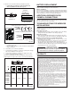
5. Thechimecanbeinstalledverticallyorhorizontally.Determineyour
preferred orientation. Locate the arrows on the front of the chime
base. Make sure one of the arrows is pointing up. (Figure 4)
6. Bring wires through the circular wire hole (D) in chime base. (Figure
4)
7. Mount chime base to wall using screws provided. Always use 2
screws for wall mounting. (Figure 4)
8. Connectwirestothescrewlesswiringconnectorasfollows:Wire“F”
toconnectorterminal“F”,wire“T”toconnectorterminal“T”andwire
“R”toconnectorterminal“R”ifinstalled.(Figure3)
9. Proceedtosectiontitled:“INSTALLWIREDPUSHBUTTON”.
EXISTING WIRED CHIME INSTALLATION
TURN OFF POWER AT SERVICE ENTRANCE.
1. Verify a 16-volt transformer with a minimum rating of 10 VA is in-
stalled.
2. Remove existing chime cover.
3. Labelallwiresinthefollowingmanner:
“F”–FrontPushbuttonWire
“T”–TransformerWire
“R”–RearPushbuttonWire(ifinstalled)
4. Disconnect all wires from existing chime base and remove from wall.
5. FollowSteps6through9undersectiontitled:“NEWWIRED
INSTALLATION.”
FIGURE5
DIODEFORFRONTDOOR
PUSHBUTTON
FIGURE6
WRAP
DIODE WIRE
AROUND
EACH
TERMINAL
SCREW
AND CLIP
EXCESS
WIRES
DIODE
SILVER BAND
RECESSED FRONT
DOOR PUSHBUTTON
SURFACE-MOUNT FRONT
DOOR PUSHBUTTON
TRANSFORMER
WIRE
FRONT
WIRE
INSTALL WIRED PUSHBUTTONS
Power to transformer should be disconnected during pushbutton
installation.
A diode must be added to the front door pushbutton so that power
will be supplied continuously to the chime.
Do not install a diode on the rear door pushbutton.
1. Locate the envelope containing the front door pushbutton diode.
(Figure 5)
2. If using an existing pushbutton(s), remove existing pushbutton(s)
from wall. If installing new pushbutton(s), refer to installation
instructions provided with pushbutton(s).
3. Gently loosen pushbutton terminal screws and install diode from Step
1 on front door pushbutton only. (Figure 5) Wrap diode wires around
terminals and clip excess wires. (Figure 6)
4. Connect transformer wire to the front door pushbutton terminal closest to
the silver band on the diode. Connect the chime wire to the other terminal.
5. Restore power to transformer.
6.
Press the pushbutton and listen for the chime to sound. If chime does
not operate, disconnect power to transformer and reverse orientation of
diode. Restore power to transformer.
7. After confirming chime operates, follow steps under section titled
“ManageChimeNotification”toselectatune,settuneduration,and
set volume.
8. Install pushbutton(s) on wall.
NOTE:Topreventshortingonmetalsiding,placeapieceof
insulating tape on the siding surface near the diode.
NOTE:Lightedpushbuttonbrightnesswillbereducedby30%-40%.
Thisisnormalandwillincreasethelifeofthebulb.
9. Place cover (B) over chime base (A) and press down to install.
A“click”willconfirmthatitissecurelyattached.(Figure1)
10. Proceedtosectiontitled:“ManageChimeNotifications”.
D
FIGURE4
VERTICAL
MOUNTING
HOLES
HORIZONTAL
MOUNTING
HOLES