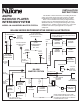
INSTALLATION INSTRUCTIONS AM/FM RADIO/CD PLAYER INTERCOM SYSTEM This booklet contains information for installing the master station. All system wiring and rough-in frames should be installed before mounting and wiring the master station. Refer to the installation instructions packaged with the rough-in frames for detailed wiring information. For more detailed information on wiring and mounting other system components (i.e., speaker, remote control, etc.
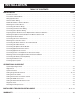
INSTALLATION TABLE OF CONTENTS INSTALLATION PAGE Contents of Carton . . . . . . . . . . . . . . . . . . . . . . . . . . . . . . . . . . . . . . . . . . . . . . . . . . . . . . . . . . . . . . . . . . . . . . . . . . . . .3 Precautions and Guidelines . . . . . . . . . . . . . . . . . . . . . . . . . . . . . . . . . . . . . . . . . . . . . . . . . . . . . . . . . . . . . . . . . . . . . .3 Wiring Specifications . . . . . . . . . . . . . . . . . . . . . . . . . . . . . . . . . . . . . . . . . . . . . . . . .
INSTALLATION CONTENTS OF CARTON Use NuTone IW-2, 22 ga. twisted pair for connecting: • Door speakers to master • Remote controls to speakers • Speaker volume control (IC901) to master • Speaker volume control (IC901) to speakers • Electronic chime audio output to master • Pushbutton to chime module Check (✓) for the following IM-4406 carton contents. ❏ IM-4406 master station ❏ Terminal board ❏ Transformer cover ❏ Hardware bag assembly containing: 2 - shoulder screws 12 - No.
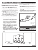
INSTALLATION (Continued) 2. Refer to Figure 2. Connect the IW-6 cable from each remote to the appropriate set of terminal screws at the master station’s terminal board. When connecting the cable to the terminal board, be sure to observe the matching of all color codes. WARNING! NEVER EXCEED A TOTAL OF 15 NUTONE 25 OHM SPEAKERS ON THIS SYSTEM. WARNING! NEVER USE STANDARD 8 OHM STEREO SPEAKERS ON THIS SYSTEM. USE ONLY NUTONE SPECIFIED SPEAKERS ON THIS MASTER.
INSTALLATION (Continued) CONNECTING VOLUME CONTROL WIRING PREPARING MASTER STATION PANEL FOR OPTIONAL DOOR RELEASE PUSHBUTTON Refer to Figure 4. If a NuTone Volume Control is installed in the system, connect the control’s IW-2 wiring to the ORN and ORN/WHT screw terminals at the master station. Only ONE NuTone speaker may be connected to each volume control. Each volume control/speaker counts as a remote station. Remember: The maximum remote connections to the Master Station is 9.
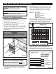
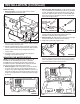
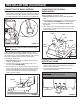
INSTALLATION (Continued) 2. Refer to Figure 10A and 10B. For rough-in frames which are recessed into the wall opening, insert two (2) shoulder screws (provided) into the front two holes in the rough-in frame. For rough-in frames which are mounted flush with the wall, insert two (2) shoulder screws into the back two holes in the rough-in frame. Model IA-29 Only 1. Refer to Figure 8. Locate the chime selector switch mounting bracket in the master unit.
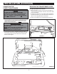
INSTALLATION (Continued) MOUNTING THE TRANSFORMER COVER CONNECTING THE POWER TRANSFORMERS ▲ ▲ CAUTION IMPORTANT: The transformer cover must be installed for proper operation of the intercom. 1. Refer to Figure 15. Remove the left front and right rear screws from the transformer enclosure. Set screws aside for later installation. 2. Position the transformer cover (with insulator positioned towards transformers) over the transformer enclosure so holes in cover align with holes in enclosure. 3.
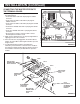
INSTALLATION (Continued) CONNECTING THE MASTER STATION TO THE TERMINAL BOARD 1. Refer to Figures 16 and 17. Plug all five connectors into the terminal board. 1. • Insert black ribbon cable with 10 pin plug into CN104 connector. 1. • Insert multi-color ribbon cable with 14 pin plug into CN102 connector. 1. • Insert multi-color ribbon cable with 9 pin plug into CN106 connector. 1. • Insert brown shielded cable with 12 pin plug into CN101 connector. 1.
INSTALLATION (Continued) CONNECTING THE RADIO ANTENNA CONNECTING THE OPTIONAL CHIME MODULE 1. Refer to Figure 18. Plug radio antenna (supplied with IR105 rough-in frame) into the 2-pin connector located on the main circuit board. Be certain the tab on the connector is facing towards the top of the master unit, as illustrated. It is now time to connect the optional chime module that you earlier installed into the master station. 1. Refer to Figure 20. Identify the front chime pushbutton wires. 2.
INSTALLATION (Continued) CONNECTING OPTIONAL ACCESSORIES CONNECTING POWER TO THE OPTIONAL CP-95 CASSETTE PLAYER 1. Refer to Figure 22. To connect an external audio source (NuTone Model CP-95 cassette, stereo system, VCR, TV, etc. with low level audio output) to the IM-4406 master station, locate the TAPE and AUXiliary inputs on the upper center of the master station’s main circuit board. 2. Connect an RCA™ phono type plug to the shielded audio cable coming from the external audio source.
INSTALLATION (Continued) MOUNTING AND CONNECTING OPTIONAL DOOR RELEASE PUSHBUTTON SECURING THE MASTER PANEL You have previously prepared the master station for the optional release pushbutton. 1. Refer to Figure 24. Feed one wire from the door release transformer and one wire from the door release mechanism through the pushbutton hole in the master station panel. ▲ ▲ 1. Refer to Figure 26. Inspect all wiring connections to make sure they are complete and correct. 2.
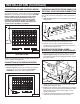
OPERATIONAL CHECKOUT SYSTEM OPERATING CONTROLS 1 21 DISPLAY: Sets the LCD display mode: CLOCK, RADIO FREQUENCY, TRACK NUMBER or TIME PLAYED. SCAN: Activates scan tuning during AM/FM operation. ▲▼ UP/DOWN TUNING: Provides manual tuning of the AM/FM radio. MEMORY 1-6 KEYS: Provides direct access to stored radio frequencies. 22 INTERCOM VOLUME: Adjusts intercom audio level throughout the system. 4 TRACK tracks.
OPERATIONAL CHECKOUT (Continued) DIGITAL CLOCK 3. Press the END CALL key. Intercom communication will end and radio audio will return to all stations in the system. 4. Press the DOOR TALK key. Radio audio will mute and audio from the initiating station will be heard at the door speaker(s) and all stations in the system. 5. Release the DOOR TALK key. Audio from the door speaker(s) will be heard at all stations in the system. 6. Press the END CALL key.
OPERATIONAL CHECKOUT (Continued) SETTING PROGRAM AUDIO CONTROLS (CONTINUED) SETTING THE BEEP TONE LEVEL The internal BEEP tone volume control has been factory set to a normal level for the BEEP tone to be heard when the CD Player operation is initiated from a remote station by using the AM/FM/CD CONTROL/END CALL key. Should that level require adjustment, use the following procedure: 1. Refer to Figure 28.
OPERATIONAL CHECKOUT (Continued) DIAGNOSTIC TESTS Remote Station Control Voltage Test – Displays the voltage at the master’s microprocessor control line. To activate, press and hold the following keys: 1. ▲ key 3. Memory 2 key 2. ▼ key 4. Release all keys Example: The following diagnostic tests have been incorporated into the NuTone IM-4406 master station to assist in system troubleshooting.
INSTALLER’S TROUBLESHOOTING GUIDE TROUBLE No radio, no intercom. (No Display). No radio, intercom working. (AM/FM indicator on.) POSSIBLE CAUSE POSSIBLE REMEDY No electrical power. Be certain 120VAC, 60Hz power has been provided to the primaries of both 801T Transformers. No less than 16VAC should be measured on the secondary of either Transformer. Defective transformer. Replace transformer. Faulty Master Station.
INSTALLER’S TROUBLESHOOTING GUIDE TROUBLE System squeals when using intercom. POSSIBLE CAUSE Shorted wire on master or remote terminal board. POSSIBLE REMEDY Check for short between terminals or loose wire. Two or more Remote Stations on Make separate cable (IW-6) runs from each Remote Station to the same wire run to Master. Master. Hum in speakers. Speakers in adjacent rooms mounted on common wall, or mounted back to back.
INSTALLER’S TROUBLESHOOTING GUIDE TROUBLE POSSIBLE CAUSE POSSIBLE REMEDY Cannot receive radio station which is received by another radio in home. Faulty antenna connection. Antenna should be located in attic and connected to tuner in Master. Check antenna connector to be sure it is connected to 2 pin connector on master. IU is displayed continuously, and the radio cycles on/off continuously. Shorted IW-6 wire going to Set remote station status switches one at a time to the OFF position.
Two Year Limited Warranty WARRANTY OWNER: NuTone warrants to the original consumer purchaser of its products that such products will be free from defects in materials or workmanship for a period of two (2) years from the date of original purchase. THERE ARE NO OTHER WARRANTIES, EXPRESS OR IMPLIED, INCLUDING, BUT NOT LIMITED TO, IMPLIED WARRANTIES OF MERCHANTABILITY OR FITNESS FOR A PARTICULAR PURPOSE.