
Installation Guide

3
Please take note this manual uses the following symbols to emphasize particular information:
NOTE: Indicates supplementary information needed to fully complete an instruction.
TABLE OF CONTENT
1. I NSTALL DUCTWORK . . . . . . . . . . . . . . . . . . . . . . . . . . . . . . . . . . . . . . . . . . . . . . . . . . . . . . . . . .3
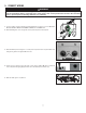
2. PREPARE THE INSTALLATION . . . . . . . . . . . . . . . . . . . . . . . . . . . . . . . . . . . . . . . . . . . . . . . . . . . . . .4
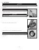
3. PREPARE THE HOOD . . . . . . . . . . . . . . . . . . . . . . . . . . . . . . . . . . . . . . . . . . . . . . . . . . . . . . . .5-6
4. INSTALL THE HOOD . . . . . . . . . . . . . . . . . . . . . . . . . . . . . . . . . . . . . . . . . . . . . . . . . . . . . . . . . . .6
5. CONNECT WIRING . . . . . . . . . . . . . . . . . . . . . . . . . . . . . . . . . . . . . . . . . . . . . . . . . . . . . . . . . . . .7
6. LIGHT BULBS . . . . . . . . . . . . . . . . . . . . . . . . . . . . . . . . . . . . . . . . . . . . . . . . . . . . . . . . . . . . . . .8
7. C LEANING AND MAINTENANCE . . . . . . . . . . . . . . . . . . . . . . . . . . . . . . . . . . . . . . . . . . . . . . . .9-10
8. OPERATION . . . . . . . . . . . . . . . . . . . . . . . . . . . . . . . . . . . . . . . . . . . . . . . . . . . . . . . . . . . . . . .10
9. WIRING DIAGRAM . . . . . . . . . . . . . . . . . . . . . . . . . . . . . . . . . . . . . . . . . . . . . . . . . . . . . . . . . . .11
10. SERVICE PA RT S . . . . . . . . . . . . . . . . . . . . . . . . . . . . . . . . . . . . . . . . . . . . . . . . . . . . . . . . . . . .11
11. WARRANTY . . . . . . . . . . . . . . . . . . . . . . . . . . . . . . . . . . . . . . . . . . . . . . . . . . . . . . . . . . . . . . .12
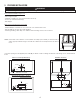
Choose where the ductwork will run between the hood and outdoors.
A straight, short duct run will allow the hood to perform most efficiently.
Long duct runs and elbows will reduce the performance of the hood. Use as few of them as possible.
Install proper-sized ductwork, elbow(s) and roof or wall cap for the type of discharge chosen. Use 2’’ metal foil duct tape to seal joints.
WARNING
!
Identifies an instruction which, if not followed, might cause serious personal injuries including possibility of death.
CAUTION
Denotes an instruction which, if not followed, may severely damage the unit and/or its components.
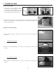
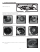
1. INSTALL DUCTWORK
HH0144A
ROOF CAP
WALL CAP
ADJUSTABLE
ELBOW
ADAPTER/
DAMPER
26” MINIMUM ABOVE
COOKING SURFACE
(28” FOR GAS RANGE)
HH0145A
WALL CAP
ADAPTER/DAMPER
26” MINIMUM ABOVE
COOKING SURFACE
(28” FOR GAS RANGE)
VERTICAL DISCHARGE
USING 6” ROUND DUCT
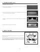
HH0146A
ROOF CAP
WALL CAP
ADJUSTABLE
ELBOW
ADAPTER/
DAMPER
EAVES CAP
26” MINIMUM ABOVE
COOKING SURFACE
(28” FOR GAS RANGE)
VERTICAL DISCHARGE
USING 3¼” X 10” DUCT
HORIZONTAL DISCHARGE
USING 3¼” X 10” DUCT
NOTE: We recommend to install the hood at a minimum of 26’’ from an electric range and at 28” from a gas range. For optimal
performance, the hood should not be installed more than 30” from cooking surface.
ABOUT THIS MANUAL