
User manual


INSTALLATION INSTRUCTIONS
READ & SAVE THESE INSTRUCTIONS!
CAUTIONS
WARNING: To reduce the risk of personal injury, do not bend
the blade brackets when installing the brackets, balancing the
blades, or cleaning the fan. Do not insert foreign objects in
between rotating fan blades.
WARNING: To reduce the risk of fire, electric shock, or
personal injury, mount to outlet box marked “Acceptable for Fan
Support” and use mounting hardware provided with the box.
WARNING: To reduce the risk of fire or electrical shock, do not
use this fan with any solid-state speed control device.
This product must be mounted and wired in compliance with all
local and national electrical codes.
Before wiring the ceiling fan, turn off electric power at the circuit
breaker or fuse box and leave off until installation is complete.
Mount outlet box so that it will support at least 35 pounds.
Note: the weight of the fan is as follows:
PFC-48 14 lbs. PFC-56 20 lbs.
LOCATION
1. When fan is installed, you must allow a minimum of 10
feet between floor and bottom of fan blades.
2. For this model, the center of the fan must be located at
least 32" from any vertical surface – wall, doors, partitions,
etc. This allows minimum clearance for fan blades.
3. Do not mount fan below, next to or between air ducts,
beams or any other obstructions which may interfere with
the natural air flow pattern created by the fan.
4. Place fans near constantly opening doors and shipping
bays to produce and “air shield” effect that helps keep out
cold air in winter and dust, odors and insects in the
summer.
5. If desired, fans can be installed directly above heat
producing machinery to reclaim the heated air.
6. For maximum air flow, fans should be located above
aisles in warehouses and storage areas.
7. Make sure fan voltage is compatible with you electrical
system.
HOW TO ASSEMBLE
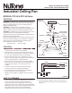
1. Locate down rod and remove spring bushing from hole in
side of rod. Locate upper canopy and remove three
screws holding fan mounting bracket in canopy. Place
upper canopy over down rod with open end toward plastic
ball hanger. Locate lower canopy and place over down rod
with open end facing away from plastic ball hanger.
Replace spring bushing into hole in side of down rod.
FIGURE 1
FIGURE 2
MOUNTING
BRACKET
UPPER CANOPY
DOWN ROD
BUSHING
SET SCREW
LOWER
CANOPY
LOCK
BOLT
MOTOR UNIT
BLADE HOLDER
GASKET
BLADE
SPRING WASHER
NUT
COTTER PIN
SPRING
WASHER
BOLT
2. Feed white, black, and green supply wires from motor
through the bushing in the down rod and up through the
down rod.
Industrial Ceiling Fan
MODELS: PFC-48 & PFC-56 Series
OUTLET BOX
GREEN
GREEN
WHITE
BLACK
SUPPLY GROUND
SUPPLY NEUTRAL
SUPPLY HOT