
Warranty

15
INSTALLATION IN EXISTING CONSTRUCTION (CONT'D)
WALL INLET INSTALLATION (CONT'D)
MAKING THE WALL INLET CUTOUT (CONT'D)
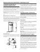
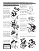
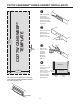
Place the template against
the wall so that it is 18”
on-center from the floor.
Use a level along the top
edge of the template to
make sure it is square to
the wall. Mark your wall
for the cutout by tracing
around the inside of the
template. Then use your
pencil to mark the screw
hole locations through
punched holes at the top
and bottom of the template.
Remove the template from
the wall.
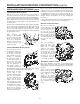
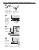
Use an awl or icepick to
punch pilot holes where
you marked the two hole
locations. Now, drill two
3⁄8” diameter holes, using
the pilot holes as the
centers. Locate and drill
these holes exactly as
marked with the template.
Also drill four pilot holes
in the four corners of the
marked area. Make sure
these holes are located
inside the marked line.
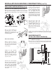
Then, using a utility knife,
score along the inside of
the marked line. For plaster
walls, score the plaster
deeply, being careful to
stay inside the marked line.
Next, use a keyhole saw
or a sabersaw to make the
cutout. Again, be extremely
careful to cut along the
inside of the marked line.
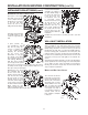
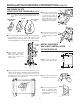
ATTACHING THE INLET MOUNTING PLATE
Reach through the inlet
hole and locate the inlet
tubing. Raise it up inside
the wall until you locate
the inlet tubing. If the inlet
is connected from the
basement, have a helper
insert the inlet tubing into
the access hole until you
can see the flexible tubing.
Then, pull the flexible
tubing through the inlet
hole and remove the low
voltage wiring from inside
the tube. If the end of the flexible tubing is not even, trim it so
that it is exactly even.
Now, remove the nail
flange (used for new
construction) from the inlet
mounting plate. Use pliers
to bend this flange along
the scored lines until you
can break it off.
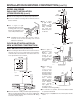
Apply cement to both the
inside of the flexible tubing
and to the outside of the
mounting plate’s tube ring.
Insert the mounting plate’s
tube ring in the flexible
tubing and twisting the
pieces as you join them
to spread the cement, and
align the mounting plate in
a vertical position.
Hold the assembly in place for a few minutes as the cement
sets; allow 5 minutes for the cement to completely dry.
Now, strip the ends of the two low voltage wires, and then
connect the wires to the screw terminals on the back of the
inlet cover. Make sure the wires are tightly secured under the
terminal screws.
AR0027
3/8”
DIA.
HOLES
AR0028A
Pilot holes must b
e
inside marked line
AR0032A
Cut
along
inside
of marked
line
AR0033A
CAUTION
When cutting into
plaster walls, make
sure the plaster is firm
and secure around
the cutout area.
AO0038
Nail Flang
e
AO0039A
AO0040
AO0041
AO0042