
Installation Guide


QTXE Series
Fan / Fluorescent
Light / Night Light
READ AND SAVE THESE INSTRUCTIONS
WARNING
TO REDUCE THE RISK OF FIRE, ELECTRIC SHOCK, OR INJURY TO PER-
SONS, OBSERVE THE FOLLOWING:
1. Use this unit only in the manner intended by the manufacturer. If you
have questions, contact the manufacturer at the address or telephone
number listed in the warranty.
2. Before servicing or cleaning unit, switch power off at service panel
and lock the service disconnecting means to prevent power from being
switched on accidentally. When the service disconnecting means cannot
be locked, securely fasten a prominent warning device, such as a tag, to
the service panel.
3. Installation work and electrical wiring must be done by a qualified per-
son(s) in accordance with all applicable codes and standards, including
fire-rated construction codes and standards.
4. Sufficient air is needed for proper combustion and exhausting of gases
through the flue (chimney) of fuel burning equipment to prevent back-
drafting. Follow the heating equipment manufacturer’s guideline and
safety standards such as those published by the National Fire Protection
Association (NFPA), and the American Society for Heating, Refrigeration
and Air Conditioning Engineers (ASHRAE), and the local code authorities.
5. When cutting or drilling into wall or ceiling, do not damage electrical
wiring and other hidden utilities.
6. Ducted fans must always be vented to the outdoors.
7. Acceptable for use over a tub or shower when connected to a GFCI (Ground
Fault Circuit Interrupter) - protected branch circuit.
8. This unit must be grounded.
CAUTION
1. For general ventilating use only. Do not use to exhaust hazardous or explosive
materials and vapors.
2. This product is designed for installation in ceilings up to a 12/12 pitch (45
degree angle). Duct connector must point up. DO NOT MOUNT THIS PROD-
UCT IN A WALL.
3. To avoid motor bearing damage and noisy and/or unbalanced impellers, keep
drywall spray, construction dust, etc. off power unit.
4. Please read specification label on product for further information and
requirements.
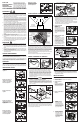
PLAN THE INSTALLATION
INSTALL HOUSING & DUCT
1a. Mount housing to joist or I-joist.
Use a pliers to bend housing TABS out to 90
0
. Hold housing in place so that
the housing tabs contact the bottom of the joist. The housing mounts with
four (4) screws or nails. Screw or nail housing to joist through lowest holes
in each mounting flange, then through highest holes. NOTE: Mounting to
I-JOIST (shown) requires use of SPACERS (included) between the highest
hole of each mounting flange and the I-joist.
TABS
SPACER
(use for mounting to I-Joist)
I-JOIST
*Purchase
separately.
INSULATION*
(Place around and
over Fan Housing.)
ROOF CAP*
(with built-in
damper)
FAN
HOUSING
POWER
CABLE*
6-IN. ROUND
DUCT*
6-IN.
ROUND
ELBOWS*
Seal gaps
around
Housing.
Seal duct
joints with
tape.
OR
Keep duct
runs short.
WALL CAP*
(with built-in
damper)
OR
1b. Mount housing anywhere between trusses, joists, or I-joists using hanger bars.
Sliding hanger bars are provided to allow for accurate positioning of housing
anywhere between framing. They can be used on all types of framing (I-joist,
standard joist, and truss construction) and span up to 24”.
HANGER
BAR (4)
SCREWS (4)
MOUNTING
CHANNEL (2)
TAB
Cooking
Equipment
Floor
COOKING AREA
Do not install above or
inside this area.
45
o
45
o
NOT FOR USE IN
A COOKING AREA.
Attach the MOUNTING CHANNELS to the housing using the screws
supplied. Make sure TABS face “up” as shown. Use the set of channel
mounting holes (marked “STD”) to mount the housing flush with the
bottom of the drywall. Use the other set of holes (not marked) to mount
the housing flush with the top of the drywall.
99045938A
1. Connect electrical wiring.
Run 120 VAC house wiring to installation location. Use proper UL ap-
proved connector to secure house wiring to wiring plate. Connect wires
as shown in wiring diagrams.
CONNECT WIRING
2. Attach damper/duct
connector.
Snap damper / duct
connector onto hous-
ing. Make sure con-
nector is flush with top
of housing and damper
flap falls closed.
3. Install 6-inch round
ductwork.
Connect 6-inch round
ductwork to damper /
duct connector. Run
ductwork to a roof cap
or wall cap. Tape all
ductwork connections
to make them secure
and air tight.
INSTALL GRILLE
1. Finish ceiling.
Install ceiling material. Cut out around housing.
2. Plug in wiring.
Plug wiring into the proper receptacles.
3. Attach grille to
housing.
Squeeze grille springs
and insert them into
slots on each side of
housing.
4. Push grille against
ceiling.
Extend hanger bars to the width of the framing.
Hold ventilator in place with the hanger bar tabs wrapping around the bottom
edge of the framing.
Nail ventilator to framing or fasten with screws (not provided) through
holes near nails.
* To ensure a noise-free mount: Secure hanger bars together with screws or
use a pliers to crimp mounting channels tightly around hanger bars.
*
SCREW (2)
HOLE FOR OPTIONAL
SCREW MOUNTING (4)
NAIL (4)
BOTTOM EDGE
OF FRAMING
Register this product at www.broan.com/
register. For Warranty Statement, or to order
Service Parts: go to broan.com or nutone.com
and type the Model in the “Model Search” field
at the top of the page. Broan, 926 W. State
Street, Hartford, WI 53027 800-637-1453
5. Remove light
lens.
Carefully insert a
small flat-blade
screwdriver
between grille and
lens. Pry lens out.
6. Install light bulbs.
Fluorescent bulbs
supplied. Purchase
a 4W incandescent
night-light bulb. In-
sert bulbs into their
sockets. Replace
lens.
TYPICAL INSTALLATIONS
Housing mounted to
I-joists.
Housing mounted any-
where between trusses
using hanger bars.
Housing mounted anywhere
between I-joists using
hanger bars.
Housing mounted to joists.
Housing mounted anywhere
between joists using
hanger bars.
Housing mounted anywhere
between trusses using
hanger bars.
CLEANING & MAINTENANCE
For quiet and efficient operation, long life, and attractive appearance - lower or
remove grille and vacuum interior of unit with the dusting brush attachment.
The motor is permanently lubricated and never needs oiling. If the motor
bearings are making excessive or unusual noises, replace the motor/blower
wheel assembly.
OPERATION
Use an on/off switch or speed control to operate this ventilator. See “Connect
Wiring” for details. Use of speed controls other than the Broan Models 78V
and 78W may cause a motor humming noise.
The ducting from this fan to the outside of the building has a strong effect
on the air flow, noise and energy use of the fan. Use the shortest, straightest
duct routing possible for best performance, and avoid installing the fan with
smaller ducts than recommended. Insulation around the ducts can reduce
energy loss and inhibit mold growth. Fans installed with existing ducts may
not achieve their rated airflow.
Use a roof cap or wall cap that has a built-in damper to reduce backdrafts.
Plan to supply the unit with proper line voltage and appropriate power cable.