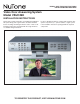
READ & SAVE THESE INSTRUCTIONS! INSTALLATION INSTRUCTIONS Video Door Answering System Model VSUC4SK INSTALLATION INSTRUCTIONS This booklet contains information for installing the TV/Monitor. All system wiring and rough-in frames should be installed before mounting and wiring the master station. Refer to the installation instructions packaged with the rough-in frames for detailed wiring information. For more detailed information on wiring and mounting other system components (i.e.
Caution RISK OF ELECTRIC SHOCK DO NOT OPEN CAUTION: TO PREVENT THE RISK OF ELECTRIC SHOCK, DO NOT REMOVE COVER (OR BACK). NO USER-SERVICEABLE PARTS INSIDE. REFER SERVICING TO QUALIFIED SERVICE PERSONNEL. WARNING: TO REDUCE THE RISK OF FIRE OR ELECTRIC SHOCK, DO NOT EXPOSE THIS APPARATUS TO RAIN OR MOISTURE.
IMPORTANT SAFETY INSTRUCTIONS 1. READ THESE INSTRUCTIONS — All the safety and operating instructions should be read before the product is operated. 2. RETAIN INSTRUCTIONS — The safety and operating instructions should be retained for future reference. 3. HEED ALL WARNINGS — All warning on the product and in the operating instructions should be adhered to. 4. FOLLOW ALL INSTRUCTIONS — All operating and use instructions should be followed. 5.
21. SAFETY CHECK — Upon completion of any service or repairs to this product, ask the service technician to perform safety checks to determine that the product is in proper operating condition. the operation instructions. Adjust only those controls that are covered by the operating instruction, as an improper adjustment of other controls may result in damage and will often require extensive work by a qualified technician to restore the product to its normal operation. 22.
Table of Contents VSUC4SK REPRESENTATIVE WIRING ILLUSTRATION . . . . . . . . . . . . . . . . . . . . . . . . . . . . . . . . . . .6 INSTALLATION . . . . . . . . . . . . . . . . . . . . . . . . . . . . . . . . . . . . . . . . . . . . . . . . . . . . . . . . . . . . . . . . . . . .6 Contents of carton . . . . . . . . . . . . . . . . . . . . . . . . . . . . . . . . . . . . . . . . . . . . . . . . . . . . . . . . . . . . .6 Precautions and Guidelines . . . . . . . . . . . . . . . . . . . . . . . . . . . . . . .
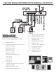
VSUC4SK SERIES REPRESENTATIVE WIRING ILLUSTRATION ¨ INSTALLATION ¨ ¨ CONTENTS OF CARTON ¨ Check (_) for following VSUC4SK carton contents: ¨ ¨ ¨ ¨ VSUC4SK TV/Monitor ¨ VSUC4SK Hardware bag assembly containing: ¨ (4) #8 x 1 1/2" screws ¨ (4) #8 x 1 1/4" screws ¨ (4) #8 x 7/8" screws ¨ (4) #8 x 2 1/4" screws (4) #8 x 1 1/2" screws (4) #8 threaded mounting shafts (4) 1/4" spacers (4) 1/2" spacers ¨ ¨ (4) 3/4" spacers VSC4S Camera VSC4S Hardware bag assembly containing: (2) #6 x 1 1/4" screws
Note to Installer: Do not discard these installation instructions. Please give all installation instructions, warranty registration and homeowner’s manual to homeowner. PRECAUTIONS AND GUIDELINES The NuTone VSUC4SK has been designed for ease of installation. Please read and follow ALL installation instructions, guidelines and precautions. Any deviation from these instructions or miswiring combinations will cause the unit to fail and all NuTone warranties will be void.
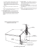
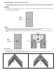
Under the Cabinet Mounting Fasten the plastic frame of the loop antenna using screws, nails, or staples (not supplied) in an open space under the cabinet. Attach the two wire lead-in cable from the loop antenna to the AM-ANT terminals on the back of the TV/Monitor. Above the Cabinet Mounting Fasten the plastic frame of the loop antenna using screws, nails, or staples (not supplied) in an open space above the cabinet. Run the two wire lead-in cable behind the cabinet to the TV/Monitor location.
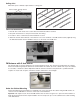
FM Folded Dipole Antenna with 20 foot lead-in The folded dipole antenna with a 20' lead is designed to be mounted in the homes attic. If additional lead-in length is needed, additional 300 ohm “twin lead” cable can be attached. Use one of the following methods to install the FM antenna. Stapling Use staples to attach twin lead wire to rafters, or joists. Insert the staple lengthwise in the plastic between the wires. Do not staple across the wire.
Ceiling Joist When attic space is limited, staple antenna to ceiling joists. Nail or Staple Through Center Twin-Lead Connection 1. Run the 20 foot twin lead to the location where the TV/Monitor will be mounted. 2. Keep twin lead at least 12" away from metal and other wiring. 3. Provide 12" extra of antenna lead at the TV/Monitor location. 4. Attach the lead-in cable terminals of the antenna to the screw terminals of the FM antenna balun (supplied).
Above the Cabinet Mounting Fasten the FM antenna using staples (not supplied) in an open space above the cabinet. Run antenna behind the cabinet to the TV/Monitor location. If access behind the cabinet is not possible, drill a hole in the top and bottom of the cabinet and “fish” Antenna through the cabinet to the TV/Monitor location. Plug the FM antenna “F” connector into the FM-ANT connector on the back of the TV/Monitor.
Camera Wiring An individual category 5 or category 6 cable must be connected from the camera to the TV/Monitor. • Maximum cable length: 250 feet. • Cable type: Category 5 or category 6 IMPORTANT: NuTone cannot be responsible for improper system operation that results from interference generated by light dimmers, fluorescent lighting fixtures, and similar electrical products. Such interference must be corrected at the source.
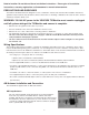
5. Separate and strip approx 1/2" of insulation from each of the eight wires in the cable. Twist the following cables together: • OR and OR/WH • GR and GR/WH • BL and BL/WH • BR and BR/WH 6. Remove the plastic back frame and rubber gasket from the camera. Position the back frame and gasket over wire and attach to the wall box using (2) #6 x 3/4" machine screws (supplied). Level the back frame before tightening screws completely. 7.
5. Separate and strip approx 1/2" of insulation from each of the eight wires in the cable. Twist the following cables together: • OR and OR/WH • GR and GR/WH • BL and BL/WH • BR and BR/WH 6. Remove the plastic back frame and rubber gasket from the camera. Position the back frame and gasket over wire and attach to the wall using (2) #6 x 1 1/4" screws (supplied). Level the back frame before tightening screws completely. 7.
• OR and OR/WH • GR and GR/WH • BL and BL/WH • BR and BR/WH 3. Attach each of the twisted pair of wires to the corresponding Camera 2 screw terminals on the back of the TV/Monitor. Tighten each screw securely. Wiring and Mounting the TV/Monitor Locate the TV/Monitor unit where the camera, TV, AM, FM and Telephone cables were previously ran.
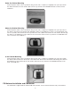
• Position the round plastic spacer at each mounting hole location. To help hold the spacers in-place, position the small diameter end of the spacer towards the TV/Monitor case. Lift and hold the TV/Monitor in position. Select a 7/8", 1 1/4", or 1 1/2" mounting screw (supplied) based on your particular installation and insert the first mounting screw into one of the mounting holes in the TV/Monitor, and tighten. • Insert the remaining 3 mounting screws (supplied) and tighten.
• Select a 1 1/2", or 2 1/4" mounting screw (supplied) based on your particular installation. Insert all four (4) mounting screws (supplied) from inside the cabinet. • Position the round plastic spacer at each mounting hole location. To help hold the spacers in-place, position the small diameter end of the spacer towards the TV/Monitor case. Lift, align the screws onto the spacers and hold the TV/Monitor in position.
Powering Up the System Once all connections throughout the system have been checked, the power cable plug can be plugged into a 120 VAC duplex outlet. Refer to the homeowner’s manual for operating instructions. Camera Volume Adjustment The VSC4S door camera is provided with a volume level adjustment set screw. The adjustment has been pre-set at the factory to provide the optimal volume level at the door camera.
FCC Information Part 15 Rules • Connect the equipment into an outlet on a circuit different from that to which the receiver is connected. This equipment has been tested and found to comply with the limits for a Class B digital device, pursuant to Part 15 of the FCC Rules. These limits are designed to provide reasonable protection against harmful interference in a residential installation.
Product specifications subject to change without notice. 4820 Red Bank Road, Cincinnati, Ohio 45227 Printed in Korea, 05/2006, Part No.
LISEZ ET CONSERVEZ CES DIRECTIVES DIRECTIVES D’INSTALLATION Portier vidéo électronique Modèle VSUC4SK DIRECTIVES D’INSTALLATION Cette brochure contient de l’information sur l’installation du télémoniteur. L’installation de tous les câbles de raccordement et boîtiers doit être achevée avant le montage et le câblage de la station principale. Reportez-vous aux directives d’installations fournies avec les boîtiers pour tous les détails de câblage.
Avertissement RISQUE DE CHOC ÉLECTRIQUE NE PAS OUVRIR AVERTISSEMENT: POUR PRÉVENIR LE RISQUE DE DÉCHARGE ÉLECTRIQUE, NE PAS RETIRER LE COUVERCLE (NI LA PLAQUE DE ARRIÈRE). NE CONTIENT AUCUNE PIÈCE POUVANT TRE RÉPARÉE PAR L’UTILISATEUR. CONFIER TOUTE RÉPARATION À UN TECHNICIEN PROFESSIONNEL. MISE EN GARDE: POUR RÉDUIRE LE RISQUE DE DÉCHARGE ÉLECTRIQUE, NE PAS EXPOSER CET APPAREIL À LA PLUIE OU À L’HUMIDITÉ.
IMPORTANTES DIRECTIVES DE SÉCURITÉ 1. LISEZ CES DIRECTIVES — Veuillez lire toutes les directives relatives à la sécurité et au fonctionnement avant d’utiliser cet appareil. fiche pourvue de deux lames, dont l’une est plus large que l’autre). La fiche ne peut être insérée que d’une seule manière dans la prise. Ce dispositif assure votre sécurité. Si vous ne parvenez pas à enfoncer dans la prise de courant, tentez d’inverser la position de la fiche.
A. Le cordon d’alimentation ou sa fiche sont endommagés. mêmes caractéristiques que celles d’origine. Des pièces non autorisées risquent de vous exposer à un incendie, à une décharge électrique ou à d’autres dangers. B. Du liquide ou des corps étrangers ont pénétré dans le boîtier de l’appareil. 21. CONTRÔLE DE SÉCURITÉ — Après un entretien ou une réparation, demandez au technicien d’effectuer un contrôle de sécurité pour s’assurer que l’appareil est en mesure de fonctionner convenablement. C.
Table des matières SCHÉMA DE CÂBLAGE REPRÉSENTATIF DU VSUC4SK . . . . . . . . . . . . . . . . . . . . . . . . . . . . . . . . . 6 INSTALLATION . . . . . . . . . . . . . . . . . . . . . . . . . . . . . . . . . . . . . . . . . . . . . . . . . . . . . . . . . . . . . . . . . . . . 6 Contenu de la boîte . . . . . . . . . . . . . . . . . . . . . . . . . . . . . . . . . . . . . . . . . . . . . . . . . . . . . . . . . . . .6 Précautions et lignes directrices . . . . . . . . . . . . . . . . . . . . . . . . . . . .
SCHÉMA DE CÂBLAGE REPRÉSENTATIF DU MODÈLE SÉRIE VSUC4SK ¨ INSTALLATION ¨ ¨ CONTENU DE LA BOÎTE ¨ Cochez (_) chacun des composants ci-dessous contenus dans le carton du VSUC4SK: ¨ ¨ ¨ Télémoniteur VSUC4SK ¨ Sac de matériel de fixation du VSUC4SK contenant: ¨ (4) vis no 8 x 1 po 1/2 ¨ (4) vis no 8 x 1 po 1/4 ¨ (4) vis no 8 x 7/8 po ¨ (4) vis no 8 x 2 po 1/4 ¨ (4) vis no 8 x 1 po 1/2 (4) tiges de montage filetées no 8 (4) entretoises de 1/4 po (4) entretoises de 1/2 po ¨ ¨ (4) entretoises
Remarque à l’intention de l’installateur : Ne jetez pas ces directives d’installation. Veuillez remettre les directives d’installation, la fiche d’enregistrement de la garantie et le manuel du propriétaire au propriétaire de la maison. PRÉCAUTIONS ET LIGNES DIRECTRICES Le VSUC4SK de NuTone a été conçu de manière à pouvoir être installé facilement. Veuillez lire TOUTES les directives d’installation, lignes directrices et précautions.
Montage au-dessus de l’armoire Fixez le support en plastique de l’antenne cadre au moyen de vis, de clous ou d’agrafes (non fournis) à un emplacement accessible au-dessus de l’armoire. Amenez une descente d’antenne à deux fils depuis l’arrière de l’armoire jusqu’à l’emplacement du télémoniteur. Si l’espace derrière l’armoire n’est pas accessible, percez un petit trou dans le haut et dans le bas de l’armoire et tirez la descente d’antenne à deux fils à travers l’armoire jusqu’à l’emplacement du télémoniteur.
Antenne FM dipôle pliante avec descente d’antenne de 20 pi L’antenne FM dipôle pliante avec descente d’antenne de 20 pi a été conçue pour être montée dans le grenier du bâtiment. S’il faut allonger la descente d’antenne, il est possible d’ajouter un câble de rallonge à deux conducteurs de 300 ohms. Utilisez l’une des méthodes ci-dessous pour l’installation de l’antenne FM. Agrafage Avec des agrafes, fixez le câble de rallonge à deux conducteurs aux chevrons ou aux solives.
Fixation à une solive Lorsque l’espace disponible dans le grenier est limité, il est possible d’agrafer l’antenne aux solives de plafond. Clou ou agrafe inséré au centre Connexion au câble à deux conducteurs 1. Amenez le câble à deux conducteurs de 20 pi jusqu’à l’emplacement de montage du télémoniteur. 2. Le câble à deux conducteurs ne doit pas être placé à moins de 12 po de toute pièce métallique ou d’un autre câble. 3.
Montage au-dessus de l’armoire Fixez l’antenne FM avec des agrafes (non fournies) à un emplacement accessible au-dessus de l’armoire. Tirez l’antenne derrière l’armoire jusqu’à l’emplacement du télémoniteur. Si l’espace derrière l’armoire n’est pas accessible, percez un petit trou dans le haut et dans le bas de l’armoire et passer l’antenne à travers l’armoire jusqu’à l’emplacement du télémoniteur. Connectez le connecteur “F” de l’antenne FM au connecteur FM-ANT à l’arrière du télémoniteur.
Câblage de la caméra Un câble séparé de catégorie 5 ou 6 doit aller de la caméra au télémoniteur. • Longueur maximale du câble: 250 pi. • Type de câble: catégorie 5 ou 6. IMPORTANT: NuTone rejette toute responsabilité relativement au fonctionnement incorrect du système résultant de l’interférence causée par un gradateur d’éclairage, un luminaire fluorescent ou un autre appareil électrique similaire. Une telle interférence doit être corrigée à la source.
5. Séparez et dénudez une longueur approximative de 1/2 po de chacun des huit fils contenus dans le câble./ Tordez les paires de fils ci-dessous ensemble: • orangé et orangé/blanc • vert et vert/blanc • noir et noir/blanc • brun et brun/blanc 6. Retirez le support arrière en plastique et le joint d’étanchéité en caoutchouc de la caméra. Positionnez le support de montage et le joint d’étanchéité sur le câble et fixez-le tout sur la boîte de jonction avec deux (2) vis mécaniques no 6 x 3/4 po (fournies).
5. Séparez et dénudez une longueur approximative de 1/2 po de chacun des huit fils contenus dans le câble./ Tordez les paires de fils ci-dessous ensemble: • orangé et orangé/blanc • vert et vert/blanc • noir et noir/blanc • brun et brun/blanc 6. Retirez le support arrière en plastique et le joint d’étanchéité en caoutchouc de la caméra. Positionnez le support de montage et le joint d’étanchéité au mur en utilisant deux (2) vis mécaniques no 6 x 1 po 1/4 (fournies).
• orangé et orangé/blanc • vert et vert/blanc • noir et noir/blanc • brun et brun/blanc 3. Fixez chaque paire de fils torsadés aux bornes à vis correspondantes de la caméra 2 à l’arrière du télémoniteur. Serrez chaque vis à fond. Câblage et montage du télémoniteur Localisez le télémoniteur à l’emplacement où les câbles de la caméra, TV, AM, FM et téléphoniques ont été amenés précédemment.
• Positionnez une entretoise ronde en plastique à l’emplacement de chacun des trous de montage. Pour que les entretoises tiennent mieux en place, positionnez le côté de l’entretoise présentant le plus petit diamètre en direction du télémoniteur. Soulevez et maintenez le télémoniteur en position.
• Sélectionnez une vis de montage de 1 po 1/2 ou de 2 po 1/4 (fournies) selon les besoins particuliers de votre installation. Insérez les quatre (4) vis de montage (fournies) à partir de l’intérieur de l’armoire. • Positionnez une entretoise ronde en plastique à l’emplacement de chacun des trous de montage. Pour que les entretoises tiennent mieux en place, positionnez le côté de l’entretoise présentant le plus petit diamètre en direction du télémoniteur.
Mise en marche du système Une fois que toutes les connexions du système ont été vérifiées, la fiche du câble d’alimentation peut être insérée dans une prise de courant double 120 V.c.a. Reportez-vous au manuel du propriétaire pour tous les détails de fonctionnement. Réglage du volume de la caméra La caméra de surveillance VSC4S est dotée d’une vis de réglage du volume. Le réglage a été effectué à l’usine afin d’assurer le niveau de volume optimal de la caméra de surveillance.
Règlement de la FCC, Partie 15 Cet appareil a été testé et reconnu conforme aux limites prévues pour des appareils numériques de classe B, tel que défini dans la partie 15 du règlement de la FCC. Ces limites sont conçues pour offrir une protection raisonnable contre des interférences dans une installation résidentielle.
Les spécifications de l’appareil sont assujetties à des changements sans préavis.