
User Manual


6
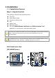
1. LED Indicators: LAN2 10. Power bottom
2. LED Indicators: LAN1 11. Line-in
3. LED Indicators: Power 12. Line-out
4. Key lock 13. Microphone in
5. eSATA Connector 14. USB 3.0 x2
6. Lan 2 15. USB 2.0 x2
7. Lan 1 16. DVI
8. VGA 17. COM port
9. Power supply switch
Step 2: Install Hard Drives
Refer to compatibility list and install HDDs. For optimal performance
consideration, install disks with the same model and storage capacity. The
available RAID level depends on the amount of disks installed.
1. Open the lid on the front of the unit enclosure.
2. Pull a HDD tray from the enclosure. See the front view figure.
3. Carefully lock the disks into the HDD tray with screws. 3 screws for each
disk. We recommend locking the screws on the bottom of the disk, instead
of the side of tray. Put the HDD tray back once you finished.
Step 3: Connect to the Network
1. Attach one end of the network cable to the RJ45 network connection. See
the rear view figure.
2. Attach the other end of the network cable to your Ethernet hub or switch.
If there are multiple networks at your facility, note the
network to which you connect
the unit. You will need this information during the setup process. Please also enable
the DHCP function within the network, as the unit
will retrieve an IP address through
DHCP by default.
Step 4: Connect the Power
1.
Attach the power cord to the power source.