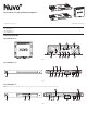
Nuvo In-Wall / In Ceiling Subwoofer Amplifiers Installation Instructions 1507315 Rev A 20190328 Part Numbers NV-SUBAMP100-xx NV-SUBAMP200-xx NV-SUBAMP500-xx AMPLIFIER FEATURES NV-SUBAMP100-xx 1 14 13 5 7 6 10 15 12 Fig. 1 NV-SUBAMP200-xx 15 19 8 17 4 6 16 7 21 5 20 10 12 11 Fig. 2 NV-SUBAMP500-xx NOTE: Power mode, Volume control, Phase control, and Crossover control are accessed on the LCD display menu using the control knob. 9 19 2 3 8 Fig.
1 Status light 7 Crossover control 12 Power cord inlet 17 12 V DC trigger input/ output 2 LCD display 8 Low-level RCA input/ output jacks 13 WLS 18 IR 3 Control knob 9 USB port 14 High-level input 19 Power button 4 Power mode switch 10 Voltage selector switch Sub terminal screws Volume control 11 Master power switch EQ selection: A - NV-SUBIC8 B - NV-SUBIW8 C - SUBIWDUAL8 20 5 15 21 Fuse 6 Phase control 16 EQ mode This instruction sheet covers the installation of th
Crossover Main Screen Power Options Screen Crossover provides an option for a low pass filter for the amplifier. Choose from one of the following options: This setting sets the power state. Choose from one of the following options: • Switch: The amplifier is always on. This is the default setting. • LFE (Default setting) • 12 V Trigger: The amplifier turns on automatically upon receiving a 12 V input signal. When the 12 V signal is removed, the amplifier automatically goes into standby mode.
INSTALLATION STEP 1: Determine the placement of the amplifier. Consider the following: • The need to place the amplifier in a rack or on a shelf. • The number of subwoofers being connected to the amplifier. • The minimum amount of space required around the amplifier to allow for adequate cooling and ventilation. • The need to access the adjustment controls to fine-tune your amplifier. STEP 2: Confirm the voltage setting for your application.
– + + Fig. 8 – Fig. 9 STEP 4: Connect the subwoofer(s) to the amplifier using either option a or option b: a. Use the SUB terminal connections (for NV-SUBAMP200-xx and NV-SUBAMP500 models) See Figure 8: 1. Strip 1/4 in. (6.4 mm) of the cable jacket on each end of two cables. 2. Loosen the RED SUB 1 screw terminal on the amplifier. 3. Insert one end of a cable securely around the screw terminal. 4. Retighten the RED SUB 1 screw terminal. 5. Repeat steps 2–4 for the BLACK SUB screw terminal. 6.
ADJUSTING THE AMPLIFIER CONTROLS STEP 1: Plug your amplifier into a functional outlet and turn the power switch to ON. If applicable to your model, a status light will illuminate when the amplifier is powered or a signal is detected, depending on the various settings selected. STEP 2: Set the power mode for the amplifier: • ON: Places the amplifier in a continuous ON status. Power can be turned on/off using the power button on the front of the amplifier. Use this mode for initial setup.
AMPLIFIER DIMENSIONS NV-SUBAMP100-xx 8.0 in. (204 mm) 7.5 in. (191 mm) 6.67 in. (170 mm) 7.1 in. (181 mm) 4.5 in. (114 mm) 2.0 in. (50.5 mm) NV-SUBAMP200-xx 16.9 in. (428 mm) 1.75 in. (44.5 mm) 8.1 in. (206 mm) NV-SUBAMP500-xx 16.9 in. (428 mm) 1.75 in. (44.5 mm) 8.1 in.
AMPLIFIER SPECIFICATIONS General Specifications Humidity Interoperability Mounting Line Input Connector Line Output Connector High Level Input Connector Trigger Input/Output Input Voltage Speaker Output USB Connection Output Power Frequency Distortion Speaker Impedance Signal-to-Noise Ratio Line Input Impedance Regulatory Approvals Safety FCC EMC UL Standard Environmental NV-SUBAMP100-xx NV-SUBAMP200-xx NV-SUBAMP500-xx 70% non-condensing Use up to two NV-SUBIC8 subwoofers Standalone or Wall Mount RCA An
REGULATORY COMPLIANCE This document contains important product safety and regulatory compliance information. To view more in-depth use and installation instructions please visit our website at www.legrand.us/nuvo.aspx. Contact Us: Technical Support: Toll free: +1.800.223.4162, opt. 3 3015 Kustom Drive Email: technicalsupport@nuvotechnologies.com Hebron, KY 41048 Toll free: +1.800.223.4162 Chat: www.legrand.
Este documento contém informação importante sobre segurança do produto e conformidade regulatória. Para ver instruções sobre uma utilização mais detalhada e instalação, visite o nosso website em www.legrand.us/nuvo.aspx. Contacte-nos: Suporte técnico: Chamada gratuita: +1.800.223.4162, opt. 3 3015 Kustom Drive E-mail: technicalsupport@nuvotechnologies.com Hebron, KY 41048 Chamada gratuita: +1.800.223.4162 Chat: www.legrand.
Important: Changes or modification to this product, not authorized by Nuvo Technologies, LLC could void the EMC compliance and negate your authority to operate the product. This product has demonstrated EMC compliance under conditions that included the use of compliant peripheral devices, USB cables, and Ethernet network cables between components. Responsible party (contact for FCC matters only): Legrand Home Systems Inc.
Europe - EU Declaration of Conformity 7 A copy of the EU Declaration of Conformity is available at: www.legrand.us/aboutus/sustainability/high-performance-buildings/eco-iconography.
Important Safety Information (English) 1. Read these instructions. 2. Keep these instructions. 3. Heed all warnings. 4. Follow all instructions. 5. Do not use this product near water or moisture or let objects or liquids enter the product. 6. Install according to manufacturer's instructions. 7. Clean only with a dry, soft cloth. 8. Do not block the ventilation openings. 9. Do not install near heat sources. 10. Protect the power cable and plug from being damaged. 11.
Disposal and Recycling Information This symbol indicates that your product must be disposed of properly according to local laws and regulations. When your product reaches its end of life, contact Nuvo Technologies or your local authorities to learn about recycling options. European Union Disposal Information This symbol above means that according to local laws and regulations your product should be disposed of separately from household waste.