
Stereo System User Manual

POWER
RENOVIA Main Main Sourc e Hub
NV-RVM
RA DIO DATA SY STEM
STANDBY AUDIO
STREAM
CTL
TX
CTL
RX
NuVoNet
USB
1
2
3 4
5
6
7
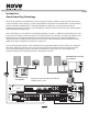
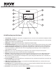
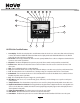
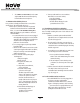
NV-RVM Main Main Source Hub Front Panel Features
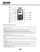
1. Power Button: This button activates the internal circuitry of the Main Main Source Hub. The NV-RVM is designed to be left in the On position.
It will remain in standby when not in use. Switch off when leaving the system unused for long periods of time, such as vacation periods, in
order to avoid unnecessary power drain.
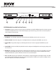
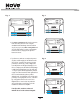
Features behind the hideaway hinged maintenance cover:
2. Standby LED: This red LED (light emitting diode), will remain lit when the NV-RVM is powered on and no zones are in use.
3. Audio Stream LED: This blue LED is a diagnostic tool. It will light while audio is streaming from the NV-RVM to any active zones.
4. Control TX LED: This green LED is a diagnostic tool indicating the transmission of control messaging from the NV-RVM to any active
zones.
5. Control RX LED: Like the Control TX LED, this yellow LED is intended as a diagnostic that will light when control messaging is being received
from an active zone.
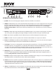
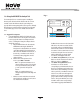
6. NuVoNet Port: This RJ45 port supports bidirectional communication between the NuVo source components, optional Hub-connected zone
Control Pad(s,) and the NV-RVM . The front panel connection is intended to be used for temporary connection of NuVoNet devices during
installation and maintenance operations. Permanent connections are located on the back panel.
7. USB: The NV-RVM completed system configuration is downloaded from a computer running the Renovia Configurator software to the Main
Source Hub using a USB cable and this jack. In this same operation, firmware updates for all NuVo system components, including connected
NuVo source components, are also delivered via this USB port.
4