nForce 680i SLI/ nForce 680i LT SLI Copyright All rights are reserved. No part of this publication may be reproduced, transmitted, transcribed, stored in a retrieval system or translated into any language or computer language, in any form or by any means, electronic, mechanical, magnetic, optical, chemical, manual or otherwise, without the prior written permission of the company. Brands and product names are trademarks or registered trademarks of their respective companies.
Mainboard nForce 680i SLI/ Mainboard nForce 680i LT SLI nForce 680i SLI/ nForce 680i LT SLI nVIDIA® nForce 680i SLI MCPs/ nForce 680i LT SLI MCPs Support Socket 775 Intel Core 2 Extreme/ CoreTM 2 Quad/ CoreTM 2 Duo/ Pentium® Extreme Edition/ Pentium® Processors ® TM User Manual Dimensions (ATX form-factor): 244mm x 305mm ( W x L ) Operating System: Windows® Vista/ Windows® XP
Mainboard nForce 680i SLI/ Mainboard nForce 680i LT SLI Things You Have To Know The images and pictures in this manual are for reference only and may vary from the product you received depending on specific hardware models, third party components and software versions. This mainboard contains very delicate IC chips. Always use a grounded wrist strap when working with the system. Do not touch any IC chip, lead, connector or other components.
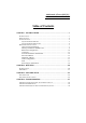
Mainboard nForce 680i SLI/ Mainboard nForce 680i LT SLI Table of Contents CHAPTER 1. GETTING STARTED .................................................... 1 INTRODUCTION ....................................................................................................... 1 SPECIFICATION ....................................................................................................... 2 CONFIGURATION ....................................................................................................
Mainboard nForce 680i SLI/ Mainboard nForce 680i LT SLI Chapter 1. Getting Started Introduction Thanks for choosing nForce 680i SLI/ nForce 680i LT SLI mainboards. They are based on ® nVIDIA nForce 680i SLI/ 680i LT SLI Northbridge and Southbridge chipsets. The nForce 680i ® TM TM TM SLI/ nForce 680i LT SLI support Intel Core 2 Extreme/ Core 2 Quad/ Core 2 Duo/ ® ® Pentium Extreme Edition/ Pentium Processors with FSB (Front Side Bus) frequencies up to 1333 MHz/ 1066 MHz/ 800 MHz.
Mainboard nForce 680i SLI/ Mainboard nForce 680i LT SLI Specification CPU Support Socket 775 Support Intel® CoreTM 2 Extreme/ CoreTM 2 Quad/ CoreTM 2 Duo/ Pentium® Extreme Edition/ Pentium® Processors Support Hyper-Threading Technology Support 1333 MHz/ 1066 MHz/ 800 MHz/ 533 MHz FSB (Front Side Bus) Frequencies Chipset Northbridge Chipset – nVIDIA® nForce 680i SLI SPP/ 680i LT SLI SPP Southbridge Chipset – nVIDIA® nForce 680i SLI MCP/ 680i LT SLI MCP I/O Controller – Winbond® W83627DHG High Definition Au
Mainboard nForce 680i SLI/ Mainboard nForce 680i LT SLI Slots Five PCI-Express interface slots for graphics cards and expansion cards 1. Two PCI-E x16 slots: supports x16 mode for true dual-graphics SLI configurations 2. One PCI-E x8 slot: supports x8 mode for future GPU physics applications 《the nForce 680i SLI only》 3.
Mainboard nForce 680i SLI/ Mainboard nForce 680i LT SLI Universal Serial Bus Six onboard USB 2.0/ 1.1 ports 《the nForce 680i SLI only》 Two front USB headers come with this mainboard for additional four USB ports Support a maximum of ten USB ports to connect USB compatible devices 《the nForce 680i SLI only》 BIOS Phoenix-Award™ BIOS Support APM 1.2 Support ACPI 2.
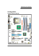
Mainboard nForce 680i SLI/ Mainboard nForce 680i LT SLI Configuration Layout of nForce 680i SLI 5
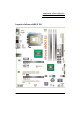
Mainboard nForce 680i SLI/ Mainboard nForce 680i LT SLI Layout of nForce 680i LT SLI 6
Mainboard nForce 680i SLI/ Mainboard nForce 680i LT SLI Hardware Installation This section will assist you in quickly installing your system hardware. Wear a wrist ground strap before handling components. Electrostatic discharge may damage the system’s components. CPU Processor Installation ® TM TM TM ® These mainboards support Intel Core 2 Extreme/ Core 2 Quad/ Core 2 Duo/ Pentium ® Extreme Edition/ Pentium Processors using a Socket 775.
Mainboard nForce 680i SLI/ Mainboard nForce 680i LT SLI FAN Headers: CPU FAN, NFORCE FAN There are several fan headers available for cooling fans on the mainboard. Here describes the two important ones only. The cooling fans play an important role in maintaining ambient temperatures in your system. The CPUFAN header is attached with a CPU cooling fan. The NFORCE FAN header is attached with the nForce SPP fan.
Mainboard nForce 680i SLI/ Mainboard nForce 680i LT SLI DIMM on the nForce 680i LT SLI How to enable Dual-Channel DDRII: 1. These mainboards provide Dual-Channel functionality for the four DIMM sockets. Enabling Dual-Channel will significantly increase your data access rate than the before. DIMM0 and DIMM1 share one channel, and DIMM2 and DIMM3 share another channel. 2. To enable Dual-Channel, you need to install memories in different channels of DIMM sockets.
Mainboard nForce 680i SLI/ Mainboard nForce 680i LT SLI 3. Lower the RAM module into the DIMM Slot and press firmly using both thumbs until the module snaps into place. 4. Repeat steps 1, 2 & 3 for the remaining RAM modules. * The pictures above are for reference only. Your actual installation may vary slightly from the pictures.
Mainboard nForce 680i SLI/ Mainboard nForce 680i LT SLI Back Panel of the nForce 680i LT SLI PS/2 Mouse & PS/2 Keyboard Ports: KB/MS These mainboards provide a standard PS/2 mouse port and a PS/2 keyboard port. S/PDIF OUT Port: SPDIF Out The S/PDIF output is capable of providing digital audio to external speakers or compressed AC3 data to an external Dolby digital decoder. Use this feature only when your stereo system has digital input function.
Mainboard nForce 680i SLI/ Mainboard nForce 680i LT SLI Audio Ports: SOUND This mainboard provides six HD Audio ports for 8/6/4/2 channel playback capability. With jack sensing, auto detecting and adjusting, the device will make it easier to Plug and Play for you. Line-In (blue) This port is for audio input and connects to external audio devices such as CD player, tape player or other audio devices when the 8/6/4/2 channel audio effects driver is enabled.
Mainboard nForce 680i SLI/ Mainboard nForce 680i LT SLI Connectors Floppy Disk Drive Connector: FLOPPY These mainboards provide a standard floppy disk drive connector (FDD) that supports 360KB/ 720KB/ 1.2MB/ 1.44MB/ 2.88 MB floppy disk drives using a FDD ribbon cable. Hard Disk Drive Connectors: IDE These mainboards provide one IDE connector that supports Ultra ATA 33/66/100/133 IDE devices. You can attach a maximum of two IDE devices, such as hard disk drive (HDD), CD-ROM, DVD-ROM, etc.
Mainboard nForce 680i SLI/ Mainboard nForce 680i LT SLI Front Panel Headers: FRONTPNL FRONTPNL Pin 1 3 5 7 9 Assignment HD_PWR (+) HAD# GND FP_RESET# N/C Function Pin Hard Disk LED (HD_LED) 2 4 6 8 10 Reset Switch (RESET) Assignment Function HDR_BLNK_GRN Front Panel Light (PWRLED) HDR_BLNK_YEL SWITCH_ON# Power Switch (PWRSW) GND Key Hard Disk LED Header (Orange): HD_LED If your case front panel has a hard drive LED cable, attach it to this header.
Mainboard nForce 680i SLI/ Mainboard nForce 680i LT SLI EZ Control Button Onboard Buttons: POWER, RESET These mainboard provide one Power Switch and one Reset Switch buttons for your convenience to turn on or restart your system. If pressing one of them, then you can start your computer easily before the mainboard is set into the case. Headers & Jumpers Case Open Warning Header: CASE OPEN This header is used to warn the user when the computer case has been previously opened.
Mainboard nForce 680i SLI/ Mainboard nForce 680i LT SLI IEEE1394 Header: IEEE1394 These mainboards provide one onboard IEEE1394 port on the back panel of your case. One additional IEEE1394 header on the mainboard for one more port on the front panel is allowed. Please connect the header by a cable for use with compatible devices.
Mainboard nForce 680i SLI/ Mainboard nForce 680i LT SLI Audio Configuration Front Audio Header: FP AUDIO The audio header supports High Definition Audio standard and provides two kinds of audio output choices, the Front Audio and the Rear Audio. The front audio supports re-tasking function.
Mainboard nForce 680i SLI/ Mainboard nForce 680i LT SLI PCI-Express x1 Interface slots: PCIE x1_1/ PCIE x1_2 The PCIE x1_1/ PCIE x1_2 slots are the PCI-Express x1 interface slots which can be supported up to x1 mode. You can insert expansion cards which are PCI-E x1 compatible onto these slots. PCI Interface Slots: PCI1/2 PCI stands for Peripheral Component Interconnect, which is a bus standard for installing expansion cards such as network card, SCSI card, etc. to these PCI slots.
Mainboard nForce 680i SLI/ Mainboard nForce 680i LT SLI ATX Power Connector: ATXPWR, ATX12V This mainboard provides two ATX power connectors, a 24-pin ATXPWR connector and an 8-pin ATX12V connector. You must use a power supply that has both of these connectors and both connectors must be attached before the system is powered on. These power connectors support several power management functions such as the instant power-on function. The connector pins are described below.
Mainboard nForce 680i SLI/ Mainboard nForce 680i LT SLI Chapter 2. BIOS Setup Introduction This section describes PHOENIX-AWARD™ BIOS Setup program which resides in the BIOS firmware. The Setup program allows users to modify the basic system configuration. The configuration information is then saved to CMOS RAM where the data is sustained by battery after power-down. The BIOS provides critical low-level support for standard devices such as disk drives, serial ports and parallel ports.
Mainboard nForce 680i SLI/ Mainboard nForce 680i LT SLI Main Menu Standard CMOS Features Include all the adjustable items in standard compatible BIOS. Advanced BIOS Features Include all the adjustable items of Award special enhanced features. Advanced Chipset Features Include all the adjustable items of chipset special features. Integrated Peripherals Include all onboard peripherals. Power Management Setup Include all the adjustable items of Green function features.
Mainboard nForce 680i SLI/ Mainboard nForce 680i LT SLI PnP/PCI Configurations Include all configurations of PCI and PnP ISA resources. System Monitor It is for monitoring the system status such as temperature, voltage, and fan speeds. Load Defaults It can load the preset system parameter values to set the system in its stable performance configurations. Set Password Set change or disable password. It allows you to limit access to the system and/or BIOS setup.
Mainboard nForce 680i SLI/ Mainboard nForce 680i LT SLI Chapter 3: Software Setup Software List Category Platform ® Windows Vista/ XP NVIDIA Chipset Driver ® Windows Vista/ XP Realtek Audio Driver Attention You don’t need to install the driver for USB 2.0 ® version if you are using Windows XP with Service Pack 2 (or higher). Software Installation Place the Driver CD into the CD-ROM drive and the Installation Utility will auto-run.
Mainboard nForce 680i SLI/ Mainboard nForce 680i LT SLI Windows® Vista Driver Windows® XP (64bit) Driver Attention ® Before you install the Realtek Audio Driver on Windows XP ® (64bit) operating system, please go to the Microsoft website to install the update for enabling HD Audio.
Mainboard nForce 680i SLI/ Mainboard nForce 680i LT SLI Windows® XP (32bit) Driver NVIDIA Chipset INF – It provides all drivers for the functions which built in both the Northbridge/ Southbridge. Realtek Audio Driver – It provides the driver of Realtek HD Audio CODEC.
Mainboard nForce 680i SLI/ Mainboard nForce 680i LT SLI 2. Click on the “User Manual” button, you can choose the manual to read. Attention: Before you read manuals, you must install the driver of Adobe Acrobat Reader 6 to browse PDF files. 3. If you click the “Browse CD” button, you can browse all the files in the Driver CD.
Mainboard nForce 680i SLI/ Mainboard nForce 680i LT SLI Chapter 4: Troubleshooting Problem 1: No power to the system. Power light does not illuminate. Fan inside power supply does not turn on. Indicator lights on keyboard are not lit. Causes: 1. Power cable is unplugged. 2. Defective power cable. 3. Power supply failure. 4. Faulty wall outlet; circuit breaker or fuse blown. Solutions: 1. Make sure power cable is securely plugged in. 2. Replace cable. 3. Contact technical support. 4.
Mainboard nForce 680i SLI/ Mainboard nForce 680i LT SLI Problem 4: System only boots from the CD-ROM. The hard disk can be read and applications can be used but booting from the hard disk is impossible. Causes: Hard Disk boot sector has been corrupted. Solutions: Back up data and applications files. Reformat the hard drive. Re-install applications and data using backup disks. Problem 5: Error message reading “SECTOR NOT FOUND” displays and the system does not allow certain data to be accessed.
Mainboard nForce 680i SLI/ Mainboard nForce 680i LT SLI Problem 10: Keyboard failure. Causes: Keyboard is disconnected. Solutions: Reconnect keyboard. Replace keyboard if you continue to experience problems. Problem 11: No color on screen. Causes: 1. Faulty Monitor. 2. CMOS incorrectly set up. Solutions: 1. If possible, connect monitor to another system. If no color appears, replace monitor. 2. Call technical support. Problem 12: The screen displays “C: drive failure.
Mainboard nForce 680i SLI/ Mainboard nForce 680i LT SLI Appendix I: 8/6/4/2 Channel Audio Effect Setup Channels Setup for Windows Vista 1. After entering the system, click the audio icon from the Windows Vista screen. 2. When your audio device is plugged, the system will detect it and show the “Speakers” tab automatically. You can see the screen like the picture below. 3. You can choose “Stereo”, “Quadraphonic”, “5.1 Speaker” or “7.1 Speaker” by your speakers in the “Speaker Configuration” item. 4.
Mainboard nForce 680i SLI/ Mainboard nForce 680i LT SLI Channels Setup for Windows XP 1. After into the system, click the audio icon from the Windows XP screen. 2. Click “Audio I/O” button, you can see the screen like the picture below. 3. You can choose 2, 4, 6 or 8 channels by your speakers. 4. You can click the “Auto test” button to test your audio devices. To take advantage of 7.1 Channel Audio Effects, you must use audio software that supports this functionality.
Mainboard nForce 680i SLI/ Mainboard nForce 680i LT SLI Appendix II: RAID Setup Introduction to RAID RAID (Redundant Array of Independent Disks) technology is a sophisticated disk management system that manages multiple disk drives. It enhances I/O performance and provides redundancy in order to prevent the loss of data in case of individual disk failure. The RAID facility on this board provides RAID 0, RAID 1, RAID 0+1, RAID JBOD, and RAID 5.
Mainboard nForce 680i SLI/ Mainboard nForce 680i LT SLI Before you create a RAID Array Before you configure your RAID Array, you have to enable the “RAID” option in the BIOS Setup Utility. Integrated Peripherals >> RAID Config >> RAID Enable >> Save & Exit Setup 1. When the screen below displays, press to enter the BIOS setup screen. 2. Move the arrow keys to the "Integrated Peripherals" item and press .
Mainboard nForce 680i SLI/ Mainboard nForce 680i LT SLI 3. After entering the sub-menu, arrow down to the "RAID Config"item. Press . 4. Enable the “RAID Enable” item and then select the SATA ports with disks that you want to use for RAID. Press to exit this screen.
Mainboard nForce 680i SLI/ Mainboard nForce 680i LT SLI 5. At the main screen arrow over to the "Save & Exit Setup" item. Press . 6. Press , and then press to finish the setup. NVIDIA RAID Setup Utility Configuration The NVIDIA RAID Setup Utility is used to configure RAID disk management into your hard disks. This section will explain how to setup and maintain your RAID disk drives.
Mainboard nForce 680i SLI/ Mainboard nForce 680i LT SLI 1. When the system boots up during the POST (Power-On Self Test), you will be given an opportunity to enter the NVIDIA RAID Setup Utility when the screen prompts you with the following message. “Press <F10> to enter RAID setup utility…” 2. Press the key to enter the NVIDIA RAID Setup Utility (note that you will only have a short window of time to press before the system continues the next step of the boot process).
Mainboard nForce 680i SLI/ Mainboard nForce 680i LT SLI Attention The “Port” and “Disk Model”, shown on these screens represent the disk drives installed on the PATA or SATA connectors and are sample data only. The actual data that displays on your screen will likely vary. Item Description á RAID Mode Choose the RAID Mode you wish to configure.
Mainboard nForce 680i SLI/ Mainboard nForce 680i LT SLI á Stripe Block Stripe block size will directly affect performance when data is written to or read by your system. • • • • • • • 4K 8K 16K 32K 64K 128K Optimal * This item is not available for RAID 1 and JBOD arrays.
Mainboard nForce 680i SLI/ Mainboard nForce 680i LT SLI Creating a New Array 1. The screen you will see upon initial configuration is the “Define a New Array” screen. over to the “RAID Mode” item and press . According to your configuration requirements, select “Mirrored” (RAID 1), “Striped” (RAID 0), “Striped Mirror“ (RAID 0+1), “Spanned” (JBOD), or “RAID 5” in the drop-down menu. Then hit . The example here is “RAID 0 (Striped)”. 2.
Mainboard nForce 680i SLI/ Mainboard nForce 680i LT SLI 3. over to the “Free Disks” selection box, and use the up/down arrow keys to select disks for your RAID array. Use the right-arrow key to move selected disks to the “Array Disks” section (the selected drive will be highlighted). You can use the left-arrow key to reverse your selection.
Mainboard nForce 680i SLI/ Mainboard nForce 680i LT SLI 4. After all of the options are properly configured, press . A confirmation box will display as shown below. Hit to continue the RAID array creation. 5. An alert box will appear as shown below. Press to clear the Master Boot Record and complete the RAID array creation.
Mainboard nForce 680i SLI/ Mainboard nForce 680i LT SLI 6. In the next page, you will see the “Array List” screen as shown below. You can press to view the details. 7. The “Array Detail” screen provides you all the information of the RAID array you created. You can press to go back to the previous page. If you want to exit NVIDIA RAID Setup Utility, press and then hit to restart your computer.
Mainboard nForce 680i SLI/ Mainboard nForce 680i LT SLI 8. When you see the screen below, please confirm the information about the RAID arrays you have created. ■ 1. If you select a RAID Mode with wrong hard disk numbers… For example, if you select “Mirrored” configure four hard disks into your array disks, and then you press go to the next step.
Mainboard nForce 680i SLI/ Mainboard nForce 680i LT SLI 2. Then you will see an alert box to notify you that you selected an invalid number of disks. In a mirrored array, you can only configure two disks at one time. You must press to go back to the main screen to reconfigure your options again. * The RAID Introduction to this manual explains disk requirements for each RAID configuration.
Mainboard nForce 680i SLI/ Mainboard nForce 680i LT SLI Deleting Array 1. If you want to delete an existing array, go to the “Array Detail screen as below. Press . 2. An alert box will display for your confirmation to delete the array. Press to delete.
Mainboard nForce 680i SLI/ Mainboard nForce 680i LT SLI 3. After the array is deleted successfully, you will return to the main screen where you can re-create a new array as shown below.
Mainboard nForce 680i SLI/ Mainboard nForce 680i LT SLI Configuring a Bootable Array Use the up/down arrow keys to select an array. Then press to specify the selected array as a bootable array. You will see a special symbol, “√”, marked in the Boot item of the highlighted array. ■ When there is only one RAID array… ■ When there are two RAID arrays or more, you can only select one.
Mainboard nForce 680i SLI/ Mainboard nForce 680i LT SLI Install Windows® XP OS onto your RAID HDDs ® This section will explain how to install the Windows XP operating system onto your RAID drives. The installation steps below will assume that your HDDs have already been attached to the SATA connectors, and your RAID arrays have already been configured using the NVIDIA RAID Setup Utility (NVIDIA RAID Setup Utility Configuration section). Download the NVIDIA RAID driver from the Albatron website. 1.
Mainboard nForce 680i SLI/ Mainboard nForce 680i LT SLI 3. Select your mainboard. The example used below is “NF 680i SLI” mainboard. 4. Click “Driver” as shown below on the left panel. Click the download icon to download the NVIDIA RAID driver (You should download the RAID driver according to your operating system). The picture below illustrates a selection for a system using a “Windows XP 32-bit Operating System”.
Mainboard nForce 680i SLI/ Mainboard nForce 680i LT SLI 5. Press the “Save” button to download the RAID zip file. You must unzip the file and save the files onto media that you can use on an existing storage device on your computer (e.g. floppy disk drive).
Mainboard nForce 680i SLI/ Mainboard nForce 680i LT SLI Install Windows® XP ® 1. During the Windows XP installation, a “Windows Setup” screen will prompt you with “Press F6 if you need to install third party SCSI or RAID driver”. Press . 2. Press when setup asks if you want to specify an additional device.
Mainboard nForce 680i SLI/ Mainboard nForce 680i LT SLI 3. Insert the media which includes the “RAID Driver” into your computer. Press to locate the appropriate OS device driver. You will install two drivers. 4. Select the “NVIDIA RAID CLASS DRIVER (required)” and press to locate this driver.
Mainboard nForce 680i SLI/ Mainboard nForce 680i LT SLI 5. When you see the screen shown as below again, press to download the second RAID driver. 6. Select the “NVIDIA nForce Storage Controller (required)” and also, press .
Mainboard nForce 680i SLI/ Mainboard nForce 680i LT SLI ® 7. You have finished RAID drivers installation. Press to continue the Windows XP setup process. 8. Follow the setup instructions and select the partition and file system where you want to install the operating system files. 9. After setup examines your disks, it will copy files to the Windows XP installation folders and restart the system.
Mainboard nForce 680i SLI/ Mainboard nForce 680i LT SLI Install Windows® Vista OS onto your RAID HDDs ® This section will explain how to install Windows Vista operating system onto your RAID drives. The installation steps below will assume that your HDDs have already been attached to the SATA connectors, and your RAID arrays have already been configured using the NVIDIA RAID Setup Utility (NVIDIA RAID Setup Utility Configuration section). Download the NVIDIA RAID driver from the Albatron website. 1.
Mainboard nForce 680i SLI/ Mainboard nForce 680i LT SLI 3. Select your mainboard. The example used below is “NF 680i SLI” mainboard. 4. Click “Driver” as shown below on the left panel. Click the download icon to download the NVIDIA RAID driver (You should download the RAID driver according to the operating system). The picture below illustrates “Windows Vista 32-bit Operating System”.
Mainboard nForce 680i SLI/ Mainboard nForce 680i LT SLI 5. Press the “Save” button to download the RAID zip file. You must unzip the file and save the files to media that you can use on an existing storage device on your computer (floppy disk drive, or USB Flash Drive).
Mainboard nForce 680i SLI/ Mainboard nForce 680i LT SLI Install Windows® Vista ® 1. During a Windows Vista installation, there will be an item “Load Driver”. Click on it and then insert the media containing the RAID Driver files into your computer. You will install two drivers. 2. Click on “Browse” to browse into the folders of the media to locate the folder with the files.
Mainboard nForce 680i SLI/ Mainboard nForce 680i LT SLI 3. Select the media which includes the RAID Drivers. 4. The example here is “floppy disk drive”. Make sure you have inserted the floppy disk including the RAID Drivers. Select “Floppy Disk Drive(A:)”. Click “OK” to load the RAID Drivers. The system will scan for the drivers automatically.
Mainboard nForce 680i SLI/ Mainboard nForce 680i LT SLI 5. Select the “NVIDIA nForce RAID Controller” and click “Next” to locate this driver. Please wait until finished. 6. When you go back to the screen shown as below, click “Load Driver” again to download the second RAID driver.
Mainboard nForce 680i SLI/ Mainboard nForce 680i LT SLI 7. Click on “Browse” to browse into the folders of the media to locate the folder with the files. 8. Select the media which includes the RAID Drivers.
Mainboard nForce 680i SLI/ Mainboard nForce 680i LT SLI 9. Select “Floppy Disk Drive(A:)” and click “OK” to load the RAID Drivers. The system will rescan for the drivers automatically. 10. Select the “NVIDIA nForce Serial ATA Controller” and click “Next” to continue. Please wait until finished.
Mainboard nForce 680i SLI/ Mainboard nForce 680i LT SLI 11. You will return to the “Install Windows” screen to continue with the installation. Follow the setup instructions and select the partition where you want to install the operating system files. ® 12. After setup examines your disks, it will copy files to the Windows Vista installation folders and restart the system. After the system is rebooted, the setup program will continue with the installation all the way to completion. ® 13.
Mainboard nForce 680i SLI/ Mainboard nForce 680i LT SLI Rebuilding a RAID Mirrored Array This section will illustrate how to replace a failed drive with a new one, and rebuild the array to restore lost data on the newly installed drive. Rebuilding only applies to fault-tolerant arrays which are RAID 1, RAID 0+1, and RAID 5 arrays. 1. Before rebuilding an array, you must connect new hard disk(s) onto your computer. 2. Power on your computer.
Mainboard nForce 680i SLI/ Mainboard nForce 680i LT SLI 5. You should see the existing RAID array on your system. Press to rebuild the array. 6. The next screen will display as below. Use up/down arrow keys to select a free disk. Press to continue.
Mainboard nForce 680i SLI/ Mainboard nForce 680i LT SLI 7. An alert box will display for your confirmation to rebuild array. Press to go to the next step. 8. A confirmation box will display as shown below. Hit to continue rebuilding the RAID array.
Mainboard nForce 680i SLI/ Mainboard nForce 680i LT SLI 9. You have successfully finished the setup of rebuilding an array in the “NVIDIA RAID Setup Utility”. Press to restart your computer. 10. During the boot process, you will see the screen below. Confirm the “Rebuild” information as shown below.
Mainboard nForce 680i SLI/ Mainboard nForce 680i LT SLI 11. The Rebuild process is automatic. You can check of the Rebuild in the following steps. Go to to “Start → All Programs → NVIDIA Corporation → NVIDIA Control Panel → Storage” under Windows. 12. A notification box will display to notify you rebuilding the array is started. Rebuilding the array will take a while. Please wait until finished.
Mainboard nForce 680i SLI/ Mainboard nForce 680i LT SLI 13. When the rebuilding is finished, make sure the “Status” item for your Rebuild Array shows “Healthy”. You have now successfully rebuilt the RAID array.
Mainboard nForce 680i SLI/ Mainboard nForce 680i LT SLI Appendix III: SLI (Scalable Link Interface) Setup Introduction NVIDIA SLI (Scalable Link Interface) is a revolutionary technology that allows two NVIDIA SLI graphics cards to work together to deliver incredible 3D graphics performance. Your new motherboard can support up to three PCI Express graphics cards, two linked using SLI and one dedicated to CPU physics.
Mainboard nForce 680i SLI/ Mainboard nForce 680i LT SLI Express auxiliary connector (6-pin connector), please contact your graphics board partner for an HDD-to-PCI Express power adaptor.
Mainboard nForce 680i SLI/ Mainboard nForce 680i LT SLI SLI graphics cards in these slots Use the following procedure to build your NVIDIA SLI-Ready PC system: 1. Install two SLI-Ready graphic cards into the two outer black PCI Express x16 slots on the motherboard. Be sure to seat the graphic cards into the connectors. Two SLI graphics cards installed in the outer two (block) PCI Express slots on the motherboard. Note the blue PCI Express slot is empty.
Mainboard nForce 680i SLI/ Mainboard nForce 680i LT SLI Three PCI Express graphics cards installed. Only the two outer cards will be SLI’ed using the SLI Connector shipped in your motherboard kit. 2.
Mainboard nForce 680i SLI/ Mainboard nForce 680i LT SLI 3. Install the NVIDIA SLI connector across the two outer graphics cards as shown below. Each SLI-Ready graphics card has an SLI finger on the upper side of the card. Install the SLI connector onto the two outer cards. Install NVIDIA SLI Software Upon power up, the operating system recognizes the new NVIDIA SLI-Ready components and displays the Found New Hardware message. Your motherboard shipped with a set of drivers that you must install.
Mainboard nForce 680i SLI/ Mainboard nForce 680i LT SLI Go to http://www.slizone.com/content/slizone/drivers.html and download the latest SLI graphics drivers. With the new drivers installed, reboot your system. After this reboot, the following SLI capable system message displays to let you know that your hardware and software components have been installed properly. Click on this message to enable your NVIDIA SLI. Enable NVIDIA SLI At this point, you need to enable NVIDIA SLI.
Mainboard nForce 680i SLI/ Mainboard nForce 680i LT SLI Select Set SLI configuration from under Performance. Click Enable SLI technology (recommended) and click Apply. The system reboots to apply the setting and display the following message upon reboot: Congratulations on your new NVIDIA SLI-Ready PC system.