nVIDIA N61 Series nVIDIA N61P/N61S/N61V Socket AM2 Processor Mainboard User’s Manual Rev: 1.
Disclaimer The intellectual property of this manual belongs to our company. The ownership of all of the products, including accessories and software etc. belong to our company. No one is permitted to copy, change, or translate without our written permission. We compiled this manual based on our careful attitude, but we can not guarantee the accuracy of the contents.
Table of Contents Chapter 1 Introduction ........................................................................ 3 1.1 Package Checklist ............................................................................................... 3 1.2 Specifications ...................................................................................................... 4 1.3 Mainboard Layout ............................................................................................... 5 1.3.1 nVIDIA N61(V1.0) .........
nVIDIA N61P/N61S/N61V User's /Manual Chapter 1 Introduction 1.1 Package Checklist Thank you for choosing our product. Please check the following packing and accessories, if there is any broken or part missing, please contact with your franchiser. • • • • • • • HDD Cable X 1 Serial ATA Cable X 1 Rear I/O Panel X 1 User's Manual X 1 Driver/Utility CD X 1 FDD Cable X 1 (Optional) Serial ATA Power Cable X 1 (Optional) The items listed above are for reference only, and are subject to change without notice.
nVIDIA N61P/N61S/N61V User's /Manual 1.2 Specifications - Socket AM2 for AMD® AthlonTM 64/AhtlonTM 64 FX/AthlonTM 64 X2/ SempronTM Processor - AMD 64 Architecture enables 32 and 64 bit computing CPU - Supports up to 1GHz Bandwidth - Supports Hyper Transport - Supports AMD CPU Cool 'n' Quiet Technology Chipset - Based on nVIDIA MCP61P/S/V chipset Graphics - Integrated nVIDIA Geforce 6100 - 2 x 240-pin DIMM slots support (for nVIDIA N61(V1.
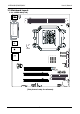
nVIDIA N61P/N61S/N61V User's /Manual 1.3 Mainboard Layout 1.3.1 nVIDIA N61(V1.
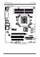
nVIDIA N61P/N61S/N61V User's /Manual 1.3.2 nVIDIA N61(V2.
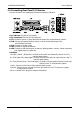
nVIDIA N61P/N61S/N61V User's /Manual 1.4 Connecting Rear Panel I/O Devices The rear I/O part of this mainboard provides the following I/O ports: • PS/2 Mouse: Connect to PS/2 mouse. • PS/2 Keyboard: Connect to PS/2 keyboard. • LPT: Connect to printer or other devices that support this communication protocol. • COM: Connect to external modem, mouse or other devices that support this communication protocol. • VGA: Connect to monitor input. • LAN: Connect to Local Area Network.
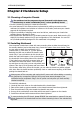
nVIDIA N61P/N61S/N61V User's /Manual Chapter 2 Hardware Setup 2.1 Choosing a Computer Chassis The mainboard and its component layouts illustrated in this chapter were based mainly on model “nVIDIA N61(V1.0)”, unless specifically stated. • Choose a chassis big enough to install this mainboard. • As some features for this mainboard are implemented by cabling connectors on the mainboard to indicators and switches or buttons on the chassis, make sure your chassis supports all the features required.
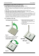
nVIDIA N61P/N61S/N61V User's /Manual 2.3 Installation of the CPU and CPU Cooler Before installing the CPU, please comply with the following conditions: 1. Please make sure that the mainboard supports the CPU. 2. Please take note of the one indented corner of the CPU. If you install the CPU in the wrong direction, the CPU will not insert properly. If this occurs, please change the insert direction of the CPU. 3. Please add an even layer of heat sink paste between the CPU and CPU cooler. 4.
nVIDIA N61P/N61S/N61V User's /Manual 2.3.2 Installation of the CPU Cooler For proper installation, please kindly refer to the instruction manuals of your CPU Cooler. 2.4 Installation of Memory Modules This mainboard provides four 240-pin DDRII (Double Data Rate) DIMM slots, and supports Dual Channel Memory Technology.
nVIDIA N61P/N61S/N61V User's /Manual 2.5 Connecting Peripheral Devices 2.5.1 Floppy and IDE Disk Drive Connectors Each of the IDE port connects up to two IDE drives at Ultra ATA 66/100/133 mode by one 40-pin, 80-conductor,and 3-connector Ultra ATA/66 ribbon cables. Connect the single end (blue connector) at the longer length of ribbon cable to the IDE port of this board, the other two ends (gray and black connector) at the shorter length of the ribbon cable to the connectors of your hard drives.
nVIDIA N61P/N61S/N61V User's /Manual Chapter 3 Jumpers & Headers Setup 3.1 Checking Jumper Settings • For a 2-pin jumper, plug the jumper cap on both pins will make it CLOSE (SHORT). Remove the jumper cap, or plug it on either pin (reserved for future use) will leave it at OPEN position. • For 3-pin jumper, pin 1~2 or pin 2~3 can be shorted by plugging the jumper cap in. How to identify the PIN1 jumpers? Please check the mainboard carefully, the PIN1 is marked by "1" or white thick line. 3.
nVIDIA N61P/N61S/N61V User's /Manual 3.4 FAN Power Connectors These connectors each provide power to the cooling fans installed in your system. CPU_FAN1: CPU Fan Power Connector SYS_FAN1: System Fan Power Connector (Options) SYS_FAN2: System Fan Power Connector These fan connectors are not jumpers. DO NOT place jumper caps on these connectors. 3.
nVIDIA N61P/N61S/N61V User's /Manual 3.6 Additional USB Port Headers Pin Pin Assignment Pin Pin Assignment 1 3 VCC Data 0- 2 4 VCC Data 1- 5 Data 0+ 6 Data 1+ 7 Ground 8 10 Ground NC 9 2 10 1 FUSB1 FUSB2 , 3.7 Front Panel Audio Connection Header This header provides the connection to audio connector at front panel. HD Audio: AC'97 Audio: Pin No.
nVIDIA N61P/N61S/N61V User's /Manual 3.8 Internal Audio Connectors Connect CD-ROM or DVD-ROM audio out to the connector. Definition CD-L GND GND CD-R 1 _ CD IN Pin No. 1 2 3 4 3.9 IR Connection Header (Optional) Connect the IrDA cable (if available) to this IR connector. Pin No.
nVIDIA N61P/N61S/N61V User's /Manual 3.10 ATX Power Input Connectors This mainboard provides two power connectors to connect power supplier. 12 2 4 1 3 GND GND - 16 - + 12V + 12V 24 + 3 . 3V + 12V + 12V 5VSB PWR OK COM + 5V COM + 5V COM + 3 . 3V +3 . 3V COM + 5V + 5V + 5V - 5V COM COM COM PS _ ON COM - 12V + 3 .
nVIDIA N61P/N61S/N61V User's /Manual Chapter 4 BIOS Setup Utility BIOS stands for Basic Input and Output System. It was once called ROM BIOS when it was stored in a Read-Only Memory (ROM) chip. Now manufacturers would like to store BIOS in EEPROM which means Electrically Erasable Programmable Memory. BIOS used in this series of mainboard is stored in EEPROM, and is the first program to run when you turn on your computer. BIOS performs the following functions: 1.
nVIDIA N61P/N61S/N61V User's /Manual 4.5 BIOS Setup — CMOS Setup Utility • In order to increase system stability and performance, our engineering staff is constantly improving the BIOS menu. The BIOS setup screens and descriptions illustrated in this manual are for your reference only, and may not completely match with what you see on your screen. • Do not change the BIOS parameters unless you fully understand its function. 4.5.
nVIDIA N61P/N61S/N61V User's /Manual • PC Health Status This setup page is the System auto detect temperature, voltage, fan, speed. • Frequency/Voltage Control This setup page is control CPU clock and frequency ratio. • Load Fail-Safe Defaults Fail-Safe Defaults indicates the value of the system parameters which the system would be in safe configuration. • Load Optimized Defaults Optimized Defaults indicates the value of the system parameters which the system would be in best performance configuration.
nVIDIA N61P/N61S/N61V User's /Manual 4.5.3 Standard CMOS Features Phoenix - AwardBIOS CMOS Setup Utility Standard CMOS Features ► ► ► ► ► ► Date (mm:dd:yy) Time (hh:mm:ss) Mon, Jun 11 2007 13 : 19 : 44 IDE IDE IDE IDE IDE IDE [MAXTOR STM380215A] [None] [None] [None] [None] [None] Channel Channel Channel Channel Channel Channel 0 0 2 2 3 3 Master Slave Master Slave Master Slave Drive A Drive B [1.44M, 3.5in.
nVIDIA N61P/N61S/N61V User's /Manual IDE HDD Auto-Detection This item allows you to detect the parameters of IDE drives by pressing key. The parameters will be shown on the screen automatically. IDE Channel 0 Master/Slave,SATA Channel 1~4 When set to [Auto], the BIOS will automatically check what kind of IDE or SATA hard drive you are using. If you want to define your own drive yourself, set it to [Manual] and make sure you fully understand the meaning of the parameters.
nVIDIA N61P/N61S/N61V User's /Manual 4.5.
nVIDIA N61P/N61S/N61V User's /Manual ・ Swap Floppy Drive If you have 2 floppy drives, you can change A to B, or change B to A. ・ Boot Up Floppy Seek During POST, BIOS will determine if the floppy disk drive installed if choose [Enable]. ・ Boot Up NumLock Status This item defines if the keyboard Num Lock key is active when your system is started. ・ Gate A20 Option [Normal]: The A20 signal is controlled by keyboard controller or chipset hardware.
nVIDIA N61P/N61S/N61V User's /Manual 4.5.5 Advanced Chipset Features Phoenix - AwardBIOS CMOS Setup Utility Advanced Chipset Features Frame Buffer Size GPU Bank Flip PMU PCIE Spread Spectrum SATA Spread Spectrum x HT Spread Spectrum SSE/SSE2 Instructions CPU Thermal-Throttling TPM Control System BIOS Cacheable 64M [64M] [Enabled] [Auto] [Disabled] [Disabled] Disabled [Enabled] [50.
nVIDIA N61P/N61S/N61V User's /Manual 4.5.
nVIDIA N61P/N61S/N61V User's /Manual OnChip IDE Channel 0 The mainboard chipset contains a PCI IDE interface with support for two IDE channels. Select “Enabled” to activate the first and/or second IDE interface. Select “Disabled” to deactivate an interface if you are going to install a primary and/or secondary add-in IDE interface. Primary Master/Slave PIO Each IDE channel supports a master device and a slave device.
nVIDIA N61P/N61S/N61V User's /Manual ・ OnChip USB This option allows you to disabled the USB function or select the mode of USB. ・ USB Memory Type Available options: [Base Memory (640K)] [Shadow]. ・ USB Keyboard Support This item allows you to select [BIOS] for using USB keyboard in DOS environment, or [OS] in OS environment. ・ USB Mouse Support This item allows you to select [BIOS] for using USB mouse in DOS environment, or [OS] in OS environment.
nVIDIA N61P/N61S/N61V User's /Manual ・ IR Transmission Delay Available options: [Disabled] [Enabled] ・ UR2 Duplex Mode This item allows user choose IR mode. Available options: [Full], [Half] ・ Use IR Pins Available options: [IR-Rx2Tx2] [RxD2,TxD2] ・ Onboard Parallel Port This item specifies the I/O address used by the parallel port. [Disabled]: This option prevents the parallel port from accessing any system resources.
nVIDIA N61P/N61S/N61V User's /Manual 4.5.
nVIDIA N61P/N61S/N61V User's /Manual ・ Power-On by Alarm The field is used to enable or disable the feature of booting up the system on a scheduled time/date. ・ Date (of Month) Alarm [0]: This option power-on the system everyday according to the time set in the “Time (hh:mm:ss) Alarm” item. [1-31]: This option selects a date you would like the system to power-on. The system will power-on on the date set, and the time set in the “Time (hh:mm:ss) Alarm” item.
nVIDIA N61P/N61S/N61V User's /Manual 4.5.9 PC Health Status Phoenix - AwardBIOS CMOS Setup Utility PC Health Status Post Show Health Status Current System Temp. Current CPU Temperture Current SYSFAN2 Speed Current CPUFAN Speed Current SYSFAN1 Speed CPU Vcore +12 V +3.3V DIMM Vcore CHIP Vcore + 5 V VBAT(V) 5VSB(V) Shutdown Temperature Disabled [Disabled] 25oC/ 78oF 39oC/102oF 0 RPM 2960 RPM 0 RPM 1.34 V 12.24 V 3.32 V 1.90 V 1.20 V 5.60 V 3.00 V 4.
nVIDIA N61P/N61S/N61V User's /Manual ► CPU Feature Click key to enter its submenu: Phoenix - AwardBIOS CMOS Setup Utility CPU Feature NPT Fid control NPT Vid control AMD K8 Cool&Quiet control [Auto] Auto [Auto] [Disabled] →←:Move ↑ ↓ Enter:Select +/-/PU/PD:Value F10:Save F5: Previous Values F6: Fail-Safe Defaults Item Help Menu Level ►► ESC:Exit F1:General Help F7: Optimized Defaults NPT Fid control This item is for setting the CPU Fid. NPT Vid control This item is for setting the CPU Vid.
nVIDIA N61P/N61S/N61V User's /Manual 4.5.11 Load Fail-Safe Defaults This option opens a dialog box that lets you install fail-safe defaults for all appropriate items in the Setup Utility: Press and the to install the defaults. Press and then to not install the defaults. The fail-safe defaults place no great demand on the system and are generally stable.
nVIDIA N61P/N61S/N61V User's /Manual To disable password, just press when you are prompted to enter password. A message will confirm the password being disabled. Once the password is disabled, the system will boot and you can enter BIOS Setup freely. ! ! PASSWORD DISABLED! Press any key to continue... 4.5.14 Save & Exit Setup Highlight this item and press to save the changes that you have made in the Setup Utility and exit the Setup Utility.
nVIDIA N61P/N61S/N61V User's /Manual Chapter 5 Driver Installation Check your package and there is Driver CD included. This CD consists of all drivers you need. In addition, this CD also include an auto detect software which can tell you which hardware is installed, and which drivers needed so that your system can function properly. Insert CD into your CD-ROM drive and the menu should appear as below.
nVIDIA N61P/N61S/N61V User's /Manual When you choose Mainboard Driver installation Utility, the drivers menu should appear as below: Back <- nForce Chipset Installation Utility Nvidia VGA Graphics Driver LAN Driver Audio Driver Exit (This picture is only for reference) From the Drivers MENU you may make 4 selections: 1. nForce Chipset Installation Utility 2. Nvidia VGA Graphics Driver 3. LAN Driver 4.