NVIDIA Tegra 250 Developer Kit Hardware Introduction and Setup Version 100113.
Contents INTRODUCTION 3 GETTING STARTED: OVERVIEW 4 UNBOXING 5 HOST PC CONFIGURATION 9 CONNECTING THE DEVKIT HW 9 “FLASHING” (INSTALLING) OPERATING SYSTEM IMAGES ONTO THE DEVKIT 12 USING YOUR BOOTED DEVKIT 18 CONNECTING THE MINI SATELLITE BOARD 19 January 2010 -2-
Introduction This manual describes the basic, initial setup of an NVIDIA Tegra 250 developer kit (devkit), and is designed to assist a new user in understanding the hardware, selecting an operating system to install to the devkit, and connect and configure the hardware to boot that operating system. Very little operating system-specific information will be found in this manual, as each operating system supported by the Tegra 250 devkit includes its own support pack with software and documentation.
Getting Started: Overview There are a few basic steps required to begin developing for the devkit: Unboxing: 1) Unpack the devkit components 2) Familiarize yourself with the components Host PC Configuration: 1) Select your desired devkit operating system 2) Download the support pack for that operating system from the NVIDIA Tegra developers website 3) Read the documentation provided with that support pack and install it to the appropriate host PC 4) Download and install any host PC support SW as required by
Unboxing Devkit Contents and Hardware Requirements As shipped, your devkit should contain the following items: • Devkit main board (rectangular circuit board containing the Tegra chip and connectors for networking, USB peripherals, storage and display devices) • 15V power adapter (USA 120V mains power connection) • Adjustable, folding, threaded WiFi antenna • Expansion board (smaller, square circuit board containing a serial port, LEDs and a few buttons) Also required to use the devkit, but not supp
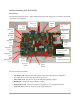
Getting Familiar with the Devkit Main Board The following diagram shows a Tegra 250 devkit main board with power connected. Important connectors are annotated: 15V power HDMI jack jack VGA WiFi Antenna jack (CRT) jack USB mini Tegra chip jack SD Card Power slot LEDs Ethernet jack USB-A jack Dual USBA jacks Expansion board connectors Headphone jack Microphone Power jack button “ACOK” configuration switch Recovery Reset button button The annotated items include: • 15V Power jack.
• USB-A jacks (3). Support for common peripherals (use of a powered USB hub is strongly recommended) • Expansion board connectors. “Header” connections for an expansion board (supplied) that adds status LEDs, copies of the power, reset and recovery buttons, and a serial port. • “ACOK” configuration switch. A configuration micro-switch that is used to adjust the power behavior of the devkit. In the left (BATT) position, the AC adapter simulates a battery, and the soft power button functions normally.
Mini Satellite Board In addition, most Tegra 250 devkits include the “mini satellite board”, which replicates the main power, reset and recovery buttons, adds a UART serial port for low-level debugging on some OSes, and switches and LEDs for common “smartbook” features like lid close, wifi on/off, etc. An appendix at the end of this document provides connection instructions.
Host PC Configuration Selecting and Downloading a Platform Support Pack Currently, there are several packs available for use with the devkit, including OS support packs and sample application SDKs. An OS support pack must be installed (or “flashed”) to the devkit in order to boot it and use it. The set of supported packs include: • An Android Éclair OS support pack. This includes scripts to install the Android OS image and associated “getting started” documentation. • A Windows CE 6.0 OS support pack.
1) Display connection. One of the following display devices should be connected. For best results, do not connect more than one of these options at a time unless directed to do so by a particular operating system pack. Be sure to check the documentation for your selected OS support pack, as some OSes may not support all of these display connections: a. Analog “VGA” display (LCD or CRT monitor) connected via the devkit’s VGA 15-pin D-sub connector. b.
Some devkit operating system images may also require additional items to be connected, including: 1) Expansion board. If required, the two ribbon cables connected to the small expansion board should be connected to the matching pair of headers on the devkit main board’s front edge. Take care to ensure that all of the pins align. 2) Ethernet. An Ethernet cable can be connected to the Ethernet jack on the left edge of the devkit main board. 3) External storage.
“Flashing” (Installing) Operating System Images onto the Devkit This documentation does not include OS-specific install instructions. Each operating system image ships in its own distribution pack, and developers should consult the documentation for that operating system image for details on how to install it. However, all of the OS support packs require the devkit device to be in recovery mode as a first step.
b. If the board does not spontaneously turn on, then press and hold the power button until the power LEDs light to turn on the device. Press until power lights turn on 3) Press and hold the recovery mode button (marked “F.R.
4) While continuing to hold the recovery mode button with one finger, use another finger (or another hand) to press the adjacent reset button. Hold the reset button down for 1-2 seconds. Press and hold Continue holding for 1-2 seconds 5) Release the reset button while still holding the recovery button.
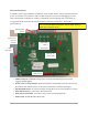
6) After a further 1-2 seconds, release the recovery button Release 7) Connect a mini-USB to USB-A cable between the host PC and the mini-USB jack on the rear-left corner of the devkit main board. 8) If this is the first time that the host PC has been used to flash a devkit device, then you may be prompted to install the USB driver for the newly-found device. This driver should have been supplied with the operating system image, as it is dependent upon the host PC OS used to flash the device.
Recovery Mode Host PC USB Driver While each OS support pack may require its own host PC OS, the most common host OS for the devkit is Windows. This section describes how to install the recovery mode driver onto a Windows host PC. If an OS support pack requires a different host PC OS (such as Linux), that pack’s documentation will describe how to install the recovery mode driver. The documentation for the support pack will indicate the location of the PC recovery mode driver to be used.
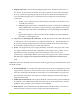
"Nvidia USB Boot-recovery driver for Mobile devices" under the heading Device Manager -> Universal Serial Bus Controllers in the device manager as follows: If you don't see this device, disconnect the devkit from the host PC, place it into recovery mode again, and restart this procedure from the beginning, as the lack of an active device in the panel indicates that the connection has not been made or that the device was not actually in recovery mode.
Using Your Booted Devkit Once you have installed a host OS onto your devkit, the platform support pack’s documentation will describe how you can develop for that devkit OS using the alreadyconfigured host PC. The platform support pack documentation for your selected OS image should also include useful information on developing for that Tegra platform. Consult it for additional details on the development process.
Connecting the Mini Satellite Board If the OS image requires it, the mini satellite board can be connected to the main board to add serial port and accessory switch functionalities.
4) Connect the remaining (upper, longer) ribbon cable to the rearmost of the two headers on the main board. Insertion should be similar to the previous ribbon cable and should look like the following figure: 5) Reconnect power to the main board. Assembly is complete.
Notice ALL NVIDIA DESIGN SPECIFICATIONS, REFERENCE BOARDS, FILES, DRAWINGS, DIAGNOSTICS, LISTS, AND OTHER DOCUMENTS (TOGETHER AND SEPARATELY, “MATERIALS”) ARE BEING PROVIDED “AS IS.” NVIDIA MAKES NO WARRANTIES, EXPRESSED, IMPLIED, STATUTORY, OR OTHERWISE WITH RESPECT TO THE MATERIALS, AND EXPRESSLY DISCLAIMS ALL IMPLIED WARRANTIES OF NONINFRINGEMENT, MERCHANTABILITY, AND FITNESS FOR A PARTICULAR PURPOSE. Information furnished is believed to be accurate and reliable.