Hardware Setup IN9 32X IN9 32X-MAX Motherboard Socket 775 BIOS Setup User’s Manual FSB 1333 MHz Triple PCI-E X16 Slots Dual Gigabit LAN 8x SATA 3Gb/s including 2x external SATA Connectors USB 2.0 / IEEE1394 7.
IN9 32X/IN9 32X-MAX User’s Manual English + Multilingual QIG P/N: 4310-0000-76 Rev. 4.00, March 2007 Copyright and Warranty Notice The information in this document is subject to change without notice and does not represent a commitment on part of the vendor, who assumes no liability or responsibility for any errors that may appear in this manual. No warranty or representation, either expressed or implied, is made with respect to the quality, accuracy or fitness for any particular part of this document.
Hardware Setup Contents 1. Hardware Setup ............................................................... 1-1 1.1 1.2 1.3 1.4 1.5 BIOS Setup Specifications............................................................................... 1-1 Motherboard Layout ..................................................................... 1-2 Choosing a Computer Chassis ....................................................... 1-3 Installing Motherboard .................................................................
2.6 Power Management Setup .......................................................... 2-21 2.7 PnP/PCI Configurations .............................................................. 2-23 2.8 Load Fail-Safe Defaults............................................................... 2-24 2.9 Load Optimized Defaults............................................................. 2-24 2.10 Set Password ........................................................................... 2-24 2.11 Save & Exit Setup...............
Hardware Setup 4.19.2 快速安裝略說.................................................................. 4-20 4.20 简体中文................................................................................. 4-21 4.20.1 规格 ............................................................................... 4-21 4.20.2 快速安装略说.................................................................. 4-22 5. Appendix .......................................................................... 5-1 BIOS Setup 5.1 POST Code Definitions.....
vi IN9 32X/IN9 32X -MAX
Hardware Setup 1. Hardware Setup 1.
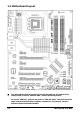
1.2 Motherboard Layout ※ The motherboard and its component layouts illustrated in this manual were mainly based on model “IN9 32X-MAX”, unless specifically stated. For model “IN9 32X”, still you may refer to “IN9 32X-MAX”. They both have the same location and definition in headers, connectors, and jumpers, except a different chipset heatsink assembly.
• Choose a chassis big enough to install this motherboard. • As some features for this motherboard are implemented by cabling connectors on the motherboard to indicators and switches or buttons on the chassis, make sure your chassis supports all the features required. • If there is a possibility of adopting some more hard drives, make sure your chassis has sufficient power and space for them. • Most chassis have alternatives for I/O shield located at the rear panel.
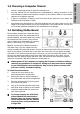
1.5 Checking Jumper Settings • • For a 2-pin jumper, plug the jumper cap on both pins will make it CLOSE (SHORT). Remove the jumper cap, or plug it on either pin (reserved for future use) will leave it at OPEN position. SHORT OPEN OPEN Pin 1~2 SHORT Pin 2~3 SHORT For 3-pin jumper, pin 1~2 or pin 2~3 can be shorted by plugging the jumper cap in. 1.5.
An onboard battery saves the CMOS memory to keep the BIOS information stays on even after disconnected your system with power source. Nevertheless, this backup battery exhausts after some five years. Once the error message like “CMOS BATTERY HAS FAILED” or “CMOS checksum error” displays on monitor, this backup battery is no longer functional and has to be renewed. To renew the backup battery: 1. Power off the system and disconnect with AC power source. 2. Remove the exhausted battery. 3.
1.6 Connecting Chassis Components 1.6.1 ATX Power Connectors These connectors provide the connection from an ATX power supply. As the plugs from the power supply fit in only one orientation, find the correct one and push firmly down into these connectors. ATXPWR1: ATX 24-Pin Power Connector The power supply with 20-pin or 24-pin cables can both be connected to this 24-pin connector. Connect from pin-1 for either type.
This header is used for connecting switches and LED indicators on the chassis front panel. Watch the power LED pin position and orientation. The mark “+” align to the pin in the figure below stands for positive polarity for the LED connection. Please pay attention when connecting these headers. A wrong orientation will only result in the LED not lighting, but a wrong connection of the switches could cause system malfunction. • HLED (Pin 1, 3): Connects to the HDD LED cable of chassis front panel.
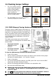
1.6.3 FAN Power Connectors These connectors each provide power to the cooling fans installed in your system. • CPUFAN1: CPU Fan Power Connector • SYSFAN1: System Fan Power Connector • AUXFAN1~4: Auxiliary Fan Power Connector ※ These fan connectors are not jumpers. DO NOT place jumper caps on these connectors.
To attach an additional chipset cooling fan for model “IN9 32X-MAX”: Inside the motherboard package you can find a pair of retention clips. These retention clips are used to fasten an additional cooling-fan attached onto the north bridge heatsink to blow away the heatwave radiated from the heatsink. As shown in the photo, you will have to buy an additional three-wire cooling fan in 40x40x10mm size: (You may have to consider the wire length according to which fan power connector you want to connect to.) 1.
1.7 Installing Hardware ※ DO NOT scratch the motherboard when installing hardware. An accidental scratch of a tiny surface-mount component may seriously damage the motherboard. ※ In order to protect the contact pins, please pay attention to these notices: 1. A maximum 20 cycles of CPU installation is recommended. 2. Never touch the contact pins with fingers or any object. 3. Always put on the cap when the CPU is not in use. 1.7.
Hardware Setup 5. Use your left hand to hold the load plate, and use your right thumb to peel the cap off. 8. Place the heatsink and fan assembly onto the socket. Align the four fasteners toward the four mounting holes on the motherboard. The cap plays an important role in protecting contact pins. In order to prevent bent pin, PUT ON the cap after operation or testing. 9. Press each of the four fasteners down into the mounting holes.
1.7.2 DDR2 Memory Slots • To reach the optimum performance in dual-channel configurations, install identical DDR2 DIMM pairs for each channel. • Install DIMMs with the same CAS latency. To reach the optimum compatibility, obtain memory modules from the same vendor. ※ Usually there is no hardware or BIOS setup required after adding or removing memory modules, but you will have to clear the CMOS memory first if any memory module related problem occurs. To install system memory: 1.
Hardware Setup 1.7.3 PCI Express X16 Add-on Slots (Install Graphics Card) These slots support the connections of graphics cards that comply with PCI Express specifications. This motherboard provides triple PCI-Express X16 slots: One PCIE graphics card installation (Normal Mode): Insert your PCIE graphics card into [PCIEXP1] (MASTER) slot. ※ The [PCIEXP3] slot supports up to X8 bandwidth only.
Two PCIE graphics cards installation (SLI Mode): To install two SLI-ready graphics cards under SLI Mode, you will need to: • Prepare two identical NVIDIA certified, SLI-ready PCI Express X16 graphics cards (the same model from the same manufacturer). • Make sure the graphics card driver supports the NVIDIA SLI technology. Download the latest driver form NVIDIA website (www.nvidia.com). • Make sure your power supply unit is sufficient to provide the minimum power required.
Hardware Setup 1.8 Connecting Peripheral Devices 1.8.1 Floppy and IDE Disk Drive Connectors The FDC1 connector connects up to two floppy drives with a 34-wire, 2-connector floppy cable. Connect the single end at the longer length of ribbon cable to the FDC1 on the board, the two connectors on the other end to the floppy disk drives connector. Generally you need only one floppy disk drive in your system.
1.8.2 Serial ATA Connectors Each SATA connector serves as one single channel to connect one SATA device by SATA cable. To connect SATA device: 1. Attach either end of the signal cable to the SATA connector on motherboard. Attach the other end to the SATA device. 2. Attach the SATA power cable to the SATA device and connect the other end from the power supply. ※ The motherboard in this photo is served for DEMO only, and may not be the same type or model as the one described in this user’s manual.
Each header supports 2x additional USB 2.0 ports by connecting bracket or cable to the rear I/O panel or the front-mounted USB ports of your chassis. Pin ※ Pin Assignment Pin Pin Assignment 1 VCC 2 VCC 3 Data0 - 4 Data1 - 5 Data0 + 6 Data1 + 7 Ground 8 Ground 10 NC Make sure the connecting cable bears the same pin assignment. 1.8.
1.8.5 Internal Audio Connectors This connector connects to the audio output of internal CD-ROM drive or add-on card. 1.8.6 Front Panel Audio Connection Header This header provides the front panel connection for HD (High Definition) Audio, yet for AC’97 Audio CODEC connection, you must carefully check the pin assignment before connecting from the front panel module. An incorrect connection may cause malfunction or even damage the motherboard.
The audio driver is originally configured to support HD Audio. For AC’97 audio connection, you may: 1. Right-click the “Realtek HD Audio Manager” icon in system tray. 2. Click “Audio I/O” tab, and then click “Connector Settings”. 3. Click “Disabled front panel jack detection”, and then click “OK” to confirm.
1.8.7 S/PDIF Output Connection Header This header provides the S/PDIF output connection to your add-on HDMI VGA card. Pin Pin Assignment 1 VCC (5V) 2 x 3 S/PDIF Out 4 Ground 1.8.8 PCI and PCI Express X1 Slot Install PCI Express X1 cards into slots “PCIE1” and/or “PCIE2”. Install PCI cards into slots “PCI1” and/or “PCI2”.
Hardware Setup 1.8.9 Guru Panel Connection Header This header is reserved for connecting abit’s exclusive Guru Panel. For more information, please refer to the included Guru Panel Installation Guide.
1.9 Onboard Indicators and Buttons 1.9.1 POST Code Displayer This is an LED device to display the “POST” Code, the acronym for Power On Self Test. The computer will execute the POST action whenever you power on the computer. The POST process is controlled by the BIOS. It is used to detect the status of the computer’s main components and peripherals. Each POST Code corresponds to different checkpoints that are also defined by the BIOS in advance.
• 5VSB/3VSB: This LED lights up when the power supply is connected with power source. • VCC: This LED lights up when the system power is on. • SLI_PWR1: This LED lights up when the “ATX4P1” connector is NOT connected with power. 1.9.3 Onboard Buttons • PWRSW1: Push this button to power on the system. • RESET1: Push this button to reset the system. IN9 32X/IN9 32X-MAX 1-23 Hardware Setup 1.9.
1.10 Connecting Rear Panel I/O Devices The rear I/O part of this motherboard provides the following I/O ports: • Mouse: Connects to PS/2 mouse. • Keyboard: Connects to PS/2 keyboard. • EZ-CCMOS1: This switch enables clearing the CMOS memory without uncovering the system chassis. To clear the CMOS memory by EZ-CCMOS1: Step 1: Power off the system. Step 2: Turn left this switch to the “Clear CMOS” position. Step 3: Turn right this switch to its default “Normal” position.
2. BIOS Setup This motherboard provides a programmable EEPROM so that you can update the BIOS utility. The BIOS (Basic Input/Output System) is a program that deals with the basic level of communication between processor and peripherals. Use the BIOS Setup program only when installing motherboard, reconfiguring system, or prompted to “Run Setup”. This chapter explains the Setup Utility of BIOS utility.
2.1 μGuru™ Utility There are two setup menus in this μGuru utility. You may switch between these two by clicking the left or right arrow key on keyboard: 2.1.1 OC Guru X X X X X X X μGuru Utility v1.00C OC Guru Intel(R) Core(TM)2 Quad CPU @ 2.66GHz Item Help ► Frequency : 2666.7MHz Setting Current SLI-Ready Memory Disabled Detected CPU Operating Speed 2666(266) - FSB Auto 1066.7 - Multiplier Factor X 10 - Estimated New CPU Clock 2666.7MHz - MEM Auto 666.
※ There will be no guaranty for the settings beyond specification. Any damage of any component on this motherboard or peripherals resulting therein is not our responsibility. - FSB This item selects the external clock frequency. Due to the specification limit of the CPU you installed, the speed you set over its standard bus speed is supported, but not guaranteed. - Multiplier Factor This item displays the multiplier factor for the CPU you installed.
Voltages Control This option allows you to switch between the default and user-defined voltages. Leave this setting at default unless the current voltage setting cannot be detected or is not correct. The option “User Define” enables you to select the following voltages manually. Click key to enter its submenu: μGuru Utility v1.00C OC Guru Voltage Control Intel(R) Core(TM)2 Quad CPU @ 2.66GHz Item Help ► Frequency : 2666.
Power Cycle Statistics Click key to enter its submenu: μGuru Utility v1.00C OC Guru Power Cycle Statistics PC Up Time PC Up Time Total PC Power Cycles PC Reset Button Cycles AC Power On Total Time AC Power Cycles 0 119 538 123 288 228 Hours Hours Cycles Cycles Hours Cycles Item Help ►► BIOS Setup :Move Enter:Select +/-/PU/PD:Value F8:OC On The Fly F10:Save ESC:Exit These items display the power cycle statistics for each element. 2.1.
[All ON]: All the LED lights on without any flashing effect. [MODE 1 ~ MODE 7]: All the LED lights on with the flashing effect by one of these modes. Temperature Monitoring Click key to enter its submenu: μGuru Utility v1.00C ABIT EQ Temperature Monitoring Reading Shutdown Shutdown Enable Temp.
Voltage Monitoring Click key to enter its submenu: :Move Enter:Select +/-/PU/PD:Value Beep Enable (*) (*) (*) (*) (*) (*) (*) (*) (*) (*) (*) (*) High Limit 1.50 2.20 1.10 1.45 1.45 1.80 1.45 14.40 14.40 6.00 3.95 6.00 F10:Save V V V V V V V V V V V V Low Limit 0.00 1.50 0.75 0.95 0.95 1.20 0.95 9.60 9.60 4.00 2.65 4.00 V V V V V V V V V V V V ESC:Exit All Voltages These items display the voltage of each element. - Shutdown Enable Use key to enable system shutdown function.
Fan Speed Monitoring Click key to enter its submenu: (*)CPU FAN Speed ( )SYS FAN Speed ( )AUX1 FAN Speed ( )AUX2 FAN Speed ( )AUX3 FAN Speed ( )AUX4 FAN Speed μGuru Utility v1.
FanEQ Control μGuru Utility v1.00C ABIT EQ FanEQ Control ► 1st FanEQ Group Press Enter ► 2nd FanEQ Group Press Enter F10:Save BIOS Setup :Move Enter:Select +/-/PU/PD:Value Item Help ►► ESC:Exit 1st FanEQ Group Click key to enter its submenu (1st FanEQ Group): μGuru Utility v1.
- Control Temperature High/Low These items set the high and low temperature limit that you want to do the fan speed control. - Fan PWM Duty Cycle High/Low These items set the high and low limit of PWM duty cycle that you want to provide the fan with. - DC Fan Voltage High/Low These items set the high and low voltage limit that you want to provide the fan with. The value of high limit must be set above the one of low limit.
2.2 Standard CMOS Features Date (mm:dd:yy) Time (hh:mm:ss) ► ► ► ► ► ► ► ► Phoenix – AwardBIOS CMOS Setup Utility Standard CMOS Features Fri, Mar 9 2007 12 : 34 : 56 None None None None None None None None Drive A Drive B Floppy 3 Mode Support Halt On 1.44M, 3.5 in.
IDE HDD Auto-Detection This item allows you to detect the parameters of IDE drives by pressing key. The parameters will be shown on the screen automatically. IDE Channel 1 Master/Slave, SATA Channel 1~6 When set to [Auto], the BIOS will automatically check what kind of IDE or SATA hard drive you are using. If you want to define your own drive yourself, set it to [Manual] and make sure you fully understand the meaning of the parameters.
[All, But Keyboard]: The system-boot will stop for all errors except a keyboard error. [All, But Diskette]: The system-boot will stop for all errors except a diskette error. [All, But Disk/Key]: The system-boot will stop for all errors except a diskette or keyboard error. Base Memory This item displays the amount of base memory installed in the system. The value of the base memory is typically 640K for systems with 640K or more memory size installed on the motherboard.
CPU Feature Click key to enter its submenu: Phoenix – AwardBIOS CMOS Setup Utility CPU Feature EIST Function Auto Thermal Control Enabled Limit CPUID MaxVal Enabled C1E Function Disabled Execute Disable Bit Enabled Virtualization Technology Enabled Frequency Unlimit Enabled Item Help :Move Enter:Select +/-/PU/PD:Value F10:Save ESC:Exit F1:General Help F5: Previous Values F6: Fail-Safe Defaults F7: Optimized Defaults EIST Function This item appears only for certain processors with the EIST (En
Back to Advanced BIOS Features Setup Menu Hard Disk Boot Priority This item selects the hard disks booting priority. By pressing key, you can enter its submenu where the hard disks detected can be selected for the booting sequence to boot up system. This item functions only when there is the option of [Hard Disk] in any one of the First/Second/Third Boot Device items.
2.
- tRRD - tRC - tWR - tWTR - tREF - tRFC Back to Advanced Chipset Features Setup Menu SLI Broadcast Aperture BIOS Setup Options: [Disabled], [Auto]. LDT Frequency Options: [1X], [2X], [3X], [4X], [5X]. System BIOS Cacheable This item enables or disables caching the system BIOS for faster execution. NVIDIA CPU Ex Select [Enable] when installed with Optimized NVIDIA Ex Graphics Driver. ※ Requires NVIDIA ForceWare Graphics Driver with NVIDIA Ex support.
2.5 Integrated Peripherals Phoenix – AwardBIOS CMOS Setup Utility Integrated Peripherals ► OnChip IDE/RAID Function Press Enter Init Display First PCI Slot OnChip USB V1.1+V2.
IDE Function Setup Click key to enter its submenu: Phoenix – AwardBIOS CMOS Setup Utility IDE Function Setup IDE 1 Controller Enabled IDE DMA Transfer Access Enabled OnChip SATA Controllers All Enabled Item Help BIOS Setup :Move Enter:Select +/-/PU/PD:Value F10:Save ESC:Exit F1:General Help F5: Previous Values F6: Fail-Safe Defaults F7: Optimized Defaults IDE 1 Controller This item allows you to enable or disable the IDE1 controller.
RAID Function This item allows you to enable or disable the RAID function. - SATA1 RAID ~ SATA6 RAID This item allows you to enable or disable the RAID function for each of the SATA 1~6 port individually. Back to Integrated Peripherals Setup Menu Init Display First This item allows you to choose the primary display card. OnChip USB This option enables or disables the USB controller. - USB Keyboard Support Select [BIOS] for the legacy operating system (such as DOS) that does not support USB keyboard.
2.6 Power Management Setup X X X X Item Help :Move Enter:Select +/-/PU/PD:Value F10:Save ESC:Exit F1:General Help F5: Previous Values F6: Fail-Safe Defaults F7: Optimized Defaults ACPI Suspend Type This item selects the type of Suspend mode. - USB Resume from S3 When set to [Enabled], this item allows you to use a USB device to wake up a system that is in the S3 (STR - Suspend To RAM) state. This item can be configured only if the item “ACPI Suspend Type” is set to [S3(STR)].
- Day of Month Alarm [0]: This option power-on the system everyday according to the time set in the “Time (hh:mm:ss) Alarm” item. [1-31]: This option selects a date you would like the system to power-on. The system will power-on on the date set, and the time set in the “Time (hh:mm:ss) Alarm” item. - Time (hh:mm:ss) Alarm This item sets the time you would like the system to power-on. Power On Function This item selects the way you want your system to power on.
HPET Support Options: [Disabled], [Enabled]. 2.
PCI/VGA Palette Snoop This item determines whether the MPEG ISA/VESA VGA cards can work with PCI/VGA or not. [Enabled]: MPEG ISA/VESA VGA cards work with PCI/VGA. [Disabled]: MPEG ISA/VESA VGA cards do not work with PCI/VGA. Maximum Payload Size This item sets the maximum TLP payload size for the PCI Express devices. 2.8 Load Fail-Safe Defaults This option loads the BIOS default values for the most stable, minimal-performance system operations. 2.
3. Driver & Utility The “Driver-&-Utility CD” that came packed with this motherboard contains drivers, utilities and software applications required for its basic and advanced features. ※ The screen shots in this chapter are snapped from model “IN9 32X-MAX”. For model “IN9 32X”, the installation items remain the same, except a different background) 3.1 CD-ROM AUTORUN To run the CD-ROM automatically: 1. Place the “Driver-&-Utility CD” into the CD-ROM drive in your system.
3.2 nVidia nForce Chipset Driver To install this program: 1. Click on the [Drivers] tab in the installation menu screen. 2. Click the [nVidia nForce Chipset Driver] item. The installation screen appears. 3. Follow the prompts on the screen to complete installation. ※ Please install this nVidia nForce Chipset Driver first after having installed the Windows operating system. 3.3 Realtek HD Audio Driver To install this program: 1. Click on the [Drivers] tab in the installation menu screen. 2.
5. Click the [Audio I/O] tab. 6. Click the pull down menu to select the channel configuration. 7. Click [OK] button to apply the Audio I/O settings and exit. 3.4 Silicon Image 3132 SATA Driver This driver provides functionality for the external SATA RAID Controller. ※ This driver installation is necessary for the devices connected through connectors “eSATA1”. 1. Click on the [Drivers] tab in the installation menu screen. 2. Click the [Silicon Image 3132 SATA Driver] item.
3.5 AirPace Wi-Fi Wireless Driver This driver provides functionality for the optional AirPace Wi-Fi wireless network adapter. ※ This driver installation appears only when the AirPace Wi-Fi wireless network adapter is connected. To install this program: 1. Click on the [Drivers] tab in the installation menu screen. 2. Click the [AirPace Wi-Fi Wireless Driver] item. The installation screen appears. 3. Follow the prompts on the screen to complete installation. 3.6 USB 2.
3.7 abit μGuru The abit μGuru combined with the optional Guru Panel allows you to access and select system performance of your system while playing games, listening music, browsing Internet or office applications in full screen with no need to stop or close the running application. To install this utility: Click on the [abit Utility] tab in the installation menu screen. 2. Click the [abit uGuru] item. The following screen appears. 3. Follow the prompts on the screen to complete installation. 4.
3.8 Build NVRaid Floppy Disk Under Windows Environment This procedure is necessary if you want to install operating system to a RAID configuration connected among “SATA1~SATA6” connectors: 1. Prepare a 3.5” floppy disk drive and connect it to “FDC1” connector on this motherboard. 2. Start install operating system. 3. Insert this driver disk into floppy disk drive when the screen instruction prompts you to install a third-party SCSI or RAID driver. 4.
3.9 Build SIL3132 SATA Floppy Disk Under Windows Environment This procedure is necessary if you want to install operating system to a SATA configuration connected between “eSATA1” connectors: 1. Prepare a 3.5” floppy disk drive and connect it to “FDC1” connector on this motherboard. 2. Start install operating system. 3. Insert this driver disk into floppy disk drive when the screen instruction prompts you to install a third-party SCSI or RAID driver. 4.
3.10 Build SIL3132 RAID Floppy Disk Under Windows Environment This procedure is necessary if you want to install operating system to a RAID configuration connected between “eSATA1” connectors: 1. Prepare a 3.5” floppy disk drive and connect it to “FDC1” connector on this motherboard. 2. Start install operating system. 3. Insert this driver disk into floppy disk drive when the screen instruction prompts you to install a third-party SCSI or RAID driver. 4.
3.11 Build A Driver Disk Under DOS Environment The “Driver Disk Maker” program bundled in the Driver-&-Utility CD is a utility to build the driver program needed for SATA controller into a floppy disk under DOS environment. This procedure is necessary only for installing Windows operating system to the hard disk connected to “eSATA1” or “SATA1~SATA6” connector. To create a driver disk: 1. Before starting, connect a 3.
3-10 IN9 32X/IN9 32X -MAX
4. Multilingual Quick Installation Guide 4.1 Français//Guide d'Installation Rapide Ce “Guide d’Installation rapide ” contient seulement l information de base dont vous pouvez avoir besoin lors de l’installation de votre carte mère abit. Pour des opérations plus avancées, vous devez vous reporter à la version complète. • [SPKR]: Connecte au câble du Haut-parleur du système. • [SLED]: Connecte au câble de la DEL de veille.
4.2 Deutsch//Kurze Installationsanleitung Diese “Kurze Installationsanleitung” enthält nur die grundlegenden Hardwareinformationen, die Sie zur Installation Ihres abit-Motherboards benötigen. Details finden Sie im ausführlichen Handbuch. Vorsichtsmaßnahmen beim Einrichten der Hardware • Vor Installation des Motherboards und Ändern von Einstellungen müssen Sie immer die Stromversorgung ausschalten und den Stecker von der Steckdose abziehen.
4.3 Italiano//Guida all’installazione rapida Questa “Guida all’installazione rapida” contiene solamente le informazioni di base sull’hardware necessarie all’installazione della scheda madre abit. Fare riferimento alla versione completa della guida per eseguire le operazioni avanzate. Precauzioni sull’installazione dell’hardware • Spegnere sempre l’unità e scollegare il cavo d’alimentazione dalla presa CA prima di installare la scheda o modificare qualsiasi impostazione.
4.4 Español//Guía rápida de instalación Esta “Guía de instalación rápida” contiene solamente la información básica sobre el hardware que puede necesitar durante la instalación de la placa base abit. Para conocer el funcionamiento avanzado, es necesario consultar la versión completa. Precauciones durante la configuración del hardware • Apague siempre la fuente de alimentación y desenchufe el cable antes de instalar la placa base o cambiar su configuración.
4.5 Português//Guia de instalação rápida Este “Guia de instalação rápida” contém apenas informação essencial sobre o hardware e necessária à instalação da sua placa principal abit. Para mais informações, terá de consultar a versão integral deste guia. Normas de segurança a ter em conta durante a montagem do hardware • Desligue sempre a fonte de alimentação e desligue o cabo de alimentação da tomada a.c. antes de instalar a placa ou alterar quaisquer definições.
4.6 Русский//Краткое руководство по установке В “Кратком руководстве по установке” содержится только основная информация о техническом обеспечении, которая вам может понадобиться при установке материнской платы abit. Описание дополнительных операций вы найдете в полной версии руководства. Предостережения по установке технического обеспечения • Перед тем, как установить плату или поменять установку, обязательно выключите питание и выдерните шнур питания из розетки.
4.7 Eesti//Kiirpaigaldusjuhend Käesolev “Kiirpaigaldusjuhend” sisaldab ainult abit-emaplaadi paigaldamiseks vajalikku riistvaraalast põhiteavet. Edasijõudnud kasutamiseks tuleb teil ikkagi pöörduda täisversiooni poole.
4.8 Latviski//Ātrās instalēšanas instrukcija Šī “Ātrās instalēšanas instrukcija” ietver tikai pamata norādes iekārtai, kas nepieciešamas, instalējot abit mātesplati. Pilnīgākai darbībai nepieciešams iegūt instrukcijas paplašināto variantu. Piesardzības pasākumi iekārtas uzstādīšanā • Vienmēr pirms plates pievienošanas vai jebkuru uzstādījumu izmaiņām izslēdziet strāvas padevi un atvienojiet vadu no maiņstrāvas barošanas avota.
4.9 Lietuvių//Trumpas instaliavimo vadovas Šiame “Trumpame instaliavimo vadove” pateikta tik esminė informacija apie techninę įrangą, kurios jums gali prireikti instaliuojant pagrindinę plokštę abit. Papildomų operacijų aprašymą rasite pilnoje vadovo versijoje.
4.10 Polski//Instrukcja szybkiej instalacji Ta “Instrukcja szybkiej instalacji” zawiera tylko podstawowe informacje dotyczące sprzętu, wymagane podczas instalacji płyty głównej abit. Przy zaawansowanych operacjach, niezbędne będzie skorzystanie z kompletnej wersji instrukcji. Środki bezpieczeństwa przy instalacji sprzętu • Przed instalacją płyty lub zmianą jakichkolwiek ustawień, należy zawsze wyłączyć zasilanie i odłączyć przewód zasilający od źródła zasilania prądem zmiennym.
4.11 Magyar//Gyorstelepítési útmutató Ez a “Gyorstelepítési útmutató” csak azt az alapvető hardver információt tartalmazza, amely az abit alaplap telepítéséhez szükséges. Az előrehaladott üzemeltetéshez, továbbra is a teljes útmutatót kell használnia. Hardver beállítási óvintézkedések • Minding kapcsolják ki a tápot ás áramtalanítsák a készüléket az alaplap telepítése vagy a beállítások módosítása előtt.
4.12 Türkçe//Hızlı Kurulum Kılavuzu Bu “Hızlı Kurulum Kılavuzu”, abit anakartınızı takmanızda gerekebilecek sadece temel donanım bilgisini içermektedir. İleri işlemler için daha geniş olan tam versiyonuna başvurmanız gerekecektir. Donanım Kurmada Alınacak Önlemler • Anakartı takmadan veya ayarları değiştirmeden önce daima • • • • güç beslemeyi kapatarak güç kablosunu elektrik prizinden çekin.
Multilingual QIG اﻟﻠﻐﺔ اﻟﻌﺮﺑﻴﺔ//دﻟﻴﻞ اﻟﺘﺮآﻴﺐ اﻟﺴﺮﻳﻊ 4.
ﻓﺎرﺳﯽ //راهﻨﻤﺎﯼ ﻧﺼﺐ ﺳﺮﻳﻊ IN9 32X/IN9 32X -MAX 4.
4.
4.16 한국어//빠른 설치 가이드 [SPKR]: 시스템 스피커 케이블에 연결하세요. [SLED]: 유휴(Suspend) LED 케이블에 연결하세요. [PWR]: 전원 스위치 케이블에 연결하세요. [PLED]: 전원 LED 케이블에 연결하세요. 본 “빠른 설치 가이드”는 빅빔 abit 메인보드 설치에 필요한 중요한 하드웨어 정보만을 포함하고 있습니다. 보다 상세한 정보 및 과정은 사용자 설명서를 참고하시기 바랍니다. • • • • 하드웨어 설치시 주의사항 추가 USB 포트 헤더: [FP-USB1], [FP-USB2] • 메인보드 설치 또는 설정을 변경하시기 전에는 추가 IEEE1394 포트 헤더: [FP-1394-1], [FP-1394-2] 항상 전 원을 끄고, AC 콘센트를 제거하시기 바랍니다. • 정전기 방지 비닐에서 메인보드를 빼 낼때는 정전기 안전 손목 접지대를 착용하고 메인보드의 가장 자리를 잡으시기 바랍니다.
4.17 Bahasa Malaysia//Panduan Pemasangan Ringkas “Panduan Pemasangan Ringkas” ini hanya mengandungi maklumat perkakasan asas yang anda mungkin perlu semasa memasang papan induk abit anda. Untuk pengendalian lanjutan, anda perlu rujuk ke versi lengkapnya. • • • • • Langkah Berjaga-jaga bagi Penyediaan Perkakasan • Sentiasa matikan bekalan kuasa dan keluarkan kord kuasa dari alur keluar AU sebelum memasang papan atau menukarkan apa-apa pengesetan.
4.
4.19 繁體中文 4.19.
4.19.
4.20 简体中文 4.20.
4.20.
5. Appendix 5.1 POST Code Definitions 5.1.
26 27 29 2B 2D 33 35 37 39 3C 3E 40 43 47 49 4E 50 52 53 55 57 59 5B 5D 60 63 65 67 69 6B 6D 6F 75 5-2 1. If Early_Init_Onboard_Generator is not defined Onboard clock generator initialization. Disable respective clock resource to empty PCI & DIMM slots. 2. Init onboard PWM 3. Init onboard H/W monitor devices Initialize INT 09 buffer 1. Program CPU internal MTRR (P6 & PII) for 0-640K memory address. 2. Initialize the APIC for Pentium class CPU. 3. Program early chipset according to CMOS setup.
76 77 7A 7C 7F (Optional Feature) Enter AWDFLASH.EXE if: -AWDFLASH is found in floppy drive -ALT+F2 is pressed Detect serial ports & parallel ports. Detect & install co-processor Init HDD write protect Switch back to text mode if full screen logo is supported -If errors occur, report errors & wait for keys -If no errors occur or F1 key is pressed to continue: Clear EPA or customization logo E8POST.ASM starts 82 83 84 85 87 89 8B 8D 8F 93 94 95 96 FF 1. Call chipset power management hook 2.
5.1.2 AC2005 POST Code Definitions POST (hex) Description Power On Sequence 8.1. Start power on sequence 8.2. Enable ATX power supply 8.3. ATX power supply ready 8.4. DDR voltage ready 8.5. Setup PWM for CPU core voltage 8.6. Assert PWM for CPU core voltage 8.7. Check CPU core voltage 8.8. CPU core voltage ready 8.9. Initial clock generator IC 8.A. North Bridge chipset voltage ready 8.B. AGP voltage ready 8.C. 3VDUAL voltage ready 8.D. VDDA 2.5V voltage ready 8.D.
5.2 Troubleshooting (How to Get Technical Support?) 5.2.1 Q & A Q: Do I need to clear the CMOS before I use a new motherboard to assemble my new computer system? A: Yes, we highly recommend that you clear the CMOS before installing a new motherboard. Please move the CMOS jumper from its default 1-2 position to 2-3 for a few seconds, and then back. When you boot up your system for the first time, follow the instructions in the user's manual to load the optimized defaults.
Q: How to get a quick response for my request on technical support? A: Please carry out a simple troubleshooting before sending “Technical Support Form”: System boot-up fails after the system had been assembled: Check the motherboard’s supporting specifications first to see if all the key components attached in your system can meet. To do so, you may: • Remove all the unnecessary add-on devices (except the CPU, VGA card, DRAM, and Power Supply), and then reboot.
• Memory configuration: Type in the memory configuration in BIOS setting. Example: Memory Timing: 2.5-3-3-7 @533MHz • Graphics information: Note Graphics card’s brand, model and driver version • Graphics card: Type in the brand and model name of your graphics card. Example: ATI RADEON X850 XT PE • Graphics driver version: Type in the driver version of your graphics card Example: Catalyst 5.12V • Power supply maker: Type in the brand and model name of your power supply unit.
5.2.
5.2.3 Contact Information Taiwan Head Office Universal ABIT Co., Ltd. No. 323, Yang Guang St., Neihu, Taipei, 114, Taiwan Tel: 886-2-8751-3380 Fax: 886-2-8751-3381 Sales: sales@abit.com.tw Austria, Czech, Romania, Bulgaria, Slovakia, Croatia, Bosnia, Serbia, Macedonia, Slovenia Universal ABIT Austria Computer GmbH Schmalbachstrasse 5, A-2201 Gerasdorf / Wien, Austria Marketing: market@abit.com.tw Tel: 43-1-7346709 Fax: 43-1-7346713 North America, South America Contact: office@abit-austria.
http://www.abit.com.tw P/N: 4310-0000-76 Rev. 4.