ForceWare Graphics Drivers Quadro FX 4500/5500 SDI User’s Guide Version 2.
NVIDIA ForceWare Graphics Drivers Quadro FX 4500/5500 SDI User’s Guide v2.0 Published by NVIDIA Corporation 2701 San Tomas Expressway Santa Clara, CA 95050 Notice ALL NVIDIA DESIGN SPECIFICATIONS, REFERENCE BOARDS, FILES, DRAWINGS, DIAGNOSTICS, LISTS, AND OTHER DOCUMENTS (TOGETHER AND SEPARATELY, “MATERIALS”) ARE BEING PROVIDED “AS IS.
Driver Utilities Quadro FX 4500/5500 SDI User’s Guide Table of Contents 1.About NVIDIA Graphics to SDI . . . . . . . . . . . . . . . . . . . . . . . . . . . . . . . . . . . . . . . . 1 2.NVIDIA Graphics-to-SDI . . . . . . . . . . . . . . . . . . . . . . . . . . . . . . . . . . . . . . . . . . . . . 3 Feature Overview . . . . . . . . . . . . . . . . . . Installing and Preparing the NVIDIA Quadro FX SDI About Your NVIDIA Quadro FX SDI . . . . . . . Installing the NVIDIA Quadro FX SDI . . . . . .
NVIDIA Drivers Quadro FX 4500/5500 SDI User’s Guide Version 2.
CHAPTER 1 About NVIDIA Graphics to SDI C H A P T E R ABOUT NVIDIA GRAPHICS TO SDI Serial Digital Interface (SDI) is a digital, uncompressed high quality video format used for film and video post production and broadcast applications. The NVIDIA Quadro® FX 4500 SDI and NVIDIA Quadro® FX 5500 SDI1 convert composited video and graphics to uncompressed 8-bit, 10-bit, or 12-bit SDI output.
CHAPTER 1 About NVIDIA Graphics to SDI System Requirements • The following operating systems are supported: • Windows® 2000 or Windows® XP. • Linux • NVIDIA Quadro FX 4500 SDI or NVIDIA Quadro FX 5500 SDI Graphics Card • PCI-Express Motherboard • NVIDIA Forceware Graphics Driver • For Windows, version 83.61 or later (NVIDIA Quadro FX 4500 SDI) • For Windows, version 91.25 or later (NVIDIA Quadro FX 5500 SDI) • For Linux, version 83.21 or later. Revision History 2 Revision Date Description 1.0 1.1 2.
CHAPTER 2 NVIDIA Graphics-to-SDI C H A P T E R NVIDIA GRAPHICS-TO-SDI This chapter provides an overview of the NVIDIA graphics-to-SDI functionality, described in the following sections: • “Feature Overview” on page 4 lists the hardware connections, supported SDI formats, and additional SDI support features of the NVIDIA Quadro FX SDI graphics card. • “Installing and Preparing the NVIDIA Quadro FX SDI” on page 6 describes how to install the NVIDIA Quadro FX SDI card and prepare it for use.
CHAPTER 2 NVIDIA Graphics-to-SDI Feature Overview Output Connections • Two BNC connections that can be configured for fill + key dual-link SDI outputs, or for single-link SDI outputs • One DVI video monitoring output • BNC connections for external sync signals Supported SDI Signal Formats • Standard Definition (SD) Modes • 487i @ 59.95 Hz (SMPTE259) NTSC • 576i @ 50.00 Hz (SMPTE259) PAL • High Definition (HD) Modes • 720p @ 23.97 Hz, 24.00 Hz, 25.00 Hz, 29.97 Hz, 30.00 Hz, and 50.00 Hz • 720p @ 59.
CHAPTER 2 NVIDIA Graphics-to-SDI Supported Output Modes • Transparent Clone Mode See “Windows–Using the Graphics to SDI Control Panel” on page 15. • Transparent Dualview Mode See “Dualview Mode” on page 53. • Extended Mode using NVIDIA SDI APIs See “API Control” on page 43. Desktop Region Adjustment Capability Lets you define a portion of the desktop to convert to SDI output. Genlock and Frame Lock Capability Lets you synchronize the SDI output to an external digital or analog sync source.
CHAPTER 2 NVIDIA Graphics-to-SDI Installing and Preparing the NVIDIA Quadro FX SDI About Your NVIDIA Quadro FX SDI The following describes the components included in your NVIDIA Quadro FX SDI product package: Cards The NVIDIA Quadro FX SDI consists of the following two cards: • NVIDIA Quadro FX 4500 or NVIDIA Quadro FX 5500 Graphics Card • NVIDIA SDI Output Card Cables In addition, you need the following cables, which should be provided with your NVIDIA Quadro FX 4500 SDI package: • (Qty 1 ea.
CHAPTER 2 NVIDIA Graphics-to-SDI Installing the NVIDIA Quadro FX SDI Step 1: Install the NVIDIA Quadro FX SDI 1 Power down the system and open the chassis cover. 2 Install the NVIDIA Quadro FX SDI card a Insert the graphics card into the x16 PCI-express slot and use a screw to secure the card’s bracket to the system chassis. b Connect the auxiliary power connector. 3 Install the NVIDIA SDI Output card.
CHAPTER 2 NVIDIA Graphics-to-SDI Step 2: Connect the Auxiliary Cabling and Monitor 1 (Optional) Install the identification color bands. Use the provided color bands to assist in properly identifying the function associated with each SMA-to-BNC cable. a Using a different color for each SMA-to-BNC cable, place the band over the SMAconnector end (the smaller end) and push up to the BNC-connector end. b Position the band snugly over the wide portion of the insulation next to the BNC connector.
CHAPTER 2 NVIDIA Graphics-to-SDI 5 Connect your display to the “south” DVI connector on the graphics card. South DVI Connector Step 3: Install the NVIDIA ForceWare Graphics Drivers If you will be installing new graphics drivers for the NVIDIA Quadro FX SDI card, it is highly recommended that you uninstall any previous version of the NVIDIA ForceWare graphics driver software before installing updated graphics drivers. 1 Follow the instructions on the NVIDIA.
CHAPTER 2 NVIDIA Graphics-to-SDI Operating NVIDIA SDI The following sections provide an overview of SDI operation: • “Understanding the Connections” on page 10 • “About the Software” on page 12 • “Recommended Operating Practices” on page 13 Understanding the Connections Figure 2.1 shows the available SDI and external sync connectors on the NVIDIA Quadro FX SDI. Key portion of a dual link SDI output Composite Genlock Sync Signal C SYNC Figure 2.
CHAPTER 2 NVIDIA Graphics-to-SDI Connecting the SDI Video Output Refer to Figure 2.1. • 4:4:4/4:2:2:4/4:4:4:4 dual-link signals are sent to the V1 Out and V2 Out connectors (corresponding to the fill + key signals respectively). • 4:2:2 single-link signals are sent to the V1 Out connector only. In application control mode, using the APIs, an additional 4:2:2 signal can be sent to the V2 Out connector.
CHAPTER 2 NVIDIA Graphics-to-SDI About the Software The NVIDIA SDI software lets you specify the • SDI signal format • Color formats • Synchronization method • Gamma correction Graphics-to-SDI functionality can be set up and controlled in two basic ways—using the NVIDIA control panel or using the NVIDIA SDI API. Using the SDI APIs The SDI application programming interface allows OpenGL applications to have full and exclusive control of the SDI output. This is also known as extended mode.
CHAPTER 2 NVIDIA Graphics-to-SDI Recommended Operating Practices This section provides some basic operating practices to follow in order to obtain the best SDI performance for your application. Initial On-Air Broadcast When starting a live broadcast of SDI video, follow the sequence below to ensure proper allocation of system resources and to prevent visual disturbances in the on air broadcast.
CHAPTER 2 NVIDIA Graphics-to-SDI Changing Video Formats When changing any of the SDI settings, visual disturbances might occur as the video resets to the new settings.
CHAPTER 3 Windows–Using the Graphics to SDI Control Panel C H A P T E R WINDOWS–USING THE GRAPHICS TO SDI CONTROL PANEL This chapter explains how to set up the NVIDIA Quadro FX SDI graphics card under Windows using the NVIDIA Graphics to SDI properties page—also known as transparent mode. It contains the following sections: • “How to Set Up the SDI Output” on page 16 provides step-by-step instructions for using the control panel to set up the SDI output.
CHAPTER 3 Windows–Using the Graphics to SDI Control Panel How to Set Up the SDI Output Basic SDI Setup To ensure proper operation, NVIDIA recommends the following • Set the desktop resolution to be the same or larger than the SDI output for better image quality • Stop background applications—such as virus scan, backup and archiving applications—prior to starting SDI output and going on air. • Close the control panel before going on air.
CHAPTER 3 Windows–Using the Graphics to SDI Control Panel Step 2: Choose a Synchronization Method Click the Sync Option arrow and then click the method you want to use to synchronize the SDI output: • Internal: The SDI output will be synchronized with the timing chosen from the SDI signal format list. • Genlock: The SDI output will be synchronized with the external sync signal. • Frame Lock: The SDI output will be synchronized with the timing chosen from the SDI signal format list.
CHAPTER 3 Windows–Using the Graphics to SDI Control Panel The Graphics to SDI property page banner indicates the status of the SDI output as well as the external synchronization signals. Figure 3.2 shows the correlation between the indicators on the banner and the actual connectors.. Graphics to SDI Property Page Banner Quadro FX 4500 SDI Connectors Figure 3.2 Connection Status Indicators The activity of the LED graphics indicates the signal status as follows: • Vid. 1 Out or Vid.
CHAPTER 3 Windows–Using the Graphics to SDI Control Panel Advanced Adjustments This section describes the following additional settings that you can control using the Graphics to SDI page: • “Adjusting the Desktop Area” on page 19 • “Applying Gamma Correction” on page 21 Adjusting the Desktop Area By default, the entire desktop is converted to SDI output. If the desktop is smaller than the size of the SDI output, it will be scaled to fit.
CHAPTER 3 Windows–Using the Graphics to SDI Control Panel 2 Click the Select Region to use option. 3 Adjust the region size. • Click and drag within the rectangular outline to adjust the position on the desktop. • Click and drag the appropriate corner or side grab handles to resize. • You can also adjust the region by specifying the X, Y, Width, and Height values in the SDI Output dialog box.
CHAPTER 3 Windows–Using the Graphics to SDI Control Panel Applying Gamma Correction To specify the gamma correction to use for the source stream: 1 In the Desktop group box, click Adjust Gamma Correction. The SDI Color Settings dialog box appears. 2 Specify the RGB Gamma values using one or more of the following methods:. • Click and drag the slider for the appropriate R, G, or B setting • Specify the R, G, or B gamma value by entering a value in the text box or using the up and down arrows.
CHAPTER 3 Windows–Using the Graphics to SDI Control Panel Synchronizing the SDI Output to an External Source You can synchronize the SDI output with other equipment in a broadcast or post production environment. Genlock Versus Frame Lock The Graphics to SDI page provides two methods for synchronizing the SDI output to a common sync source—Genlock and Frame lock. Using Genlock Genlock synchronizes the pixel scanning of the SDI output to an external synchronization source.
CHAPTER 3 Windows–Using the Graphics to SDI Control Panel Synchronization Instructions Basic Setup Summary The following are the basic steps to synchronize the SDI output. 1 Connect the external sync source to the appropriate BNC connector on the graphics card. See “Understanding the Connections” on page 10 for instructions on connecting the external sync signal to the graphics card. 2 Configure the sync source. Use the NVIDIA Graphics to SDI property page to configure the SDI output synchronization.
CHAPTER 3 Windows–Using the Graphics to SDI Control Panel Detecting the External Sync Signal Source The software should automatically detect the external sync signal. When it does, the sync format information appears in the Genlock/Framelock format text box. If you have both SDI and Composite signals connected • The software automatically chooses the SDI signal. • If you want to switch to the composite signal, click the arrow in the Genlock/ Framelock format group box and then click COMP Sync.
CHAPTER 3 Windows–Using the Graphics to SDI Control Panel Adding a Delay to the Signal You can introduce a slight delay in the genlocked or frame locked SDI output. For example, if delivery of video from other equipment is delayed because of greater cable length, you can introduce a delay in the SDI output from this card so that both deliveries are in sync. To introduce a synchronization delay: 1 Click Advanced Options from the Graphics to SDI page. The SDI Advanced Options window appears. Figure 3.
CHAPTER 3 Windows–Using the Graphics to SDI Control Panel Viewing System Information To view information about the graphics card and the installed driver software, click Advanced Options from the Graphics to SDI page. The General tab shows the graphics card model, firmware version, driver version and current SDI resolution.‘ Figure 3.7 SDI Advanced Options—General tab 26 NVIDIA Corporation Quadro FX 4500/5500 SDI User’s Guide– Version 2.
CHAPTER 3 Windows–Using the Graphics to SDI Control Panel Using SDI Under Dualview In the default configuration, the SDI output is a clone of the display output. The NVIDIA Quadro FX 4500 SDI graphics card also supports Dualview mode, where the desktop extends across two monitors. About Dualview Mode Under Dualview mode, you can define one large desktop that extends from the display to the SDI output.
CHAPTER 3 Windows–Using the Graphics to SDI Control Panel How to Enable Dualview Mode To enable Dualview mode: 1 Right-click the desktop, then from the pop-up menu, click Properties. The Display Properties page appears. 2 From the Display Properties page, click the Settings tab. The Settings page appears. 3 Click the monitor icon that is grayed (not attached) and then check the Extend my Windows desktop onto this monitor check box. 4 Click OK or Apply.
CHAPTER 3 Windows–Using the Graphics to SDI Control Panel Changing SDI Settings Under Dualview To change the SDI settings once Dualview is enabled, 1 Open the Microsoft Display Properties Settings page as described in steps 1 and 2 above 2 Right-click Display #2, then from the pop-up menu click Properties. 3 Click the Quadro FX 4500 SDI or Quadro FX 5500 SDI tab and then click the Graphics to SDI tree item from the side menu. You can now change the SDI settings for the 2nd display, or SDI output.
CHAPTER 3 Windows–Using the Graphics to SDI Control Panel 30 NVIDIA Corporation Quadro FX 4500/5500 SDI User’s Guide– Version 2.
CHAPTER 4 Linux—Using the Graphics to Video Out Control Panel C H A P T E R LINUX—USING THE GRAPHICS TO VIDEO OUT CONTROL PANEL This chapter explains how to set up the NVIDIA Quadro FX 4500 SDI graphics card under Linux using the NVIDIA Graphics to Video Out properties page1. It contains the following sections: • “How to Set Up the SDI Output” on page 32 provides step-by-step instructions for using the control panel to set up the SDI output.
CHAPTER 4 Linux—Using the Graphics to Video Out Control Panel How to Set Up the SDI Output Basic SDI Setup To ensure proper operation, NVIDIA recommends the following • Set the desktop resolution to be the same or larger than the SDI output for better image quality • Stop background applications—such as virus scan, backup and archiving applications—prior to starting SDI output and going on air. • Close the control panel before going on air.
CHAPTER 4 Linux—Using the Graphics to Video Out Control Panel The Graphics to Video Out page appears. Figure 4.2 Graphics to Video Out Page Step 2: Choose a Synchronization Method From the Sync Options group box, click the Sync Mode list arrow and then click the method you want to use to synchronize the SDI output: • Free Running: The SDI output will be synchronized with the timing chosen from the SDI signal format list. • Genlock: The SDI output will be synchronized with the external sync signal.
CHAPTER 4 Linux—Using the Graphics to Video Out Control Panel Step 3: Choose the Output Options • Output Video Format controls the video resolution, field rate, and SMPTE signalling standard for the outgoing video stream. • Output Data Format controls the color model, data packing, and alpha or z components in the outgoing video stream. 1 Specify the Output Video Format From the Output Options group box, click the Output Video Format arrow and then click the signal format you want to use.
CHAPTER 4 Linux—Using the Graphics to Video Out Control Panel The activity of the LED graphics indicates the signal status as follows: • Vid. 1 Out or Vid. 2 Out Status Meaning Off (gray) SDI output is not in use Blinking Green SDI output is active and is in HD mode. Blinking Yellow SDI output is active and is in SD mode. Status Meaning Off (gray) SDI synchronization signal is not present or not detected. Blinking Green SDI synchronization signal is detected in HD mode.
CHAPTER 4 Linux—Using the Graphics to Video Out Control Panel Advanced Adjustments This section describes the following additional settings that you can control using the Graphics to SDI page: • “Adjusting the Desktop Area” on page 36 • “Customizing the Color Space Conversion” on page 37 Adjusting the Desktop Area By default, the entire desktop is converted to SDI output. If the desktop is smaller than the size of the SDI output, it will be scaled to fit.
CHAPTER 4 Linux—Using the Graphics to Video Out Control Panel Customizing the Color Space Conversion To set your own RGB color space conversion: 1 Click the Color Space Conversion tree item from the side menu. The Color Space Conversion page appears. 2 Check Override default Color Space Conversion. 3 Click the Initialize Color Space Conversion with list arrow and then click one of the standards to use as a starting point: ITU-601, 709, 177, or Identity.
CHAPTER 4 Linux—Using the Graphics to Video Out Control Panel Synchronizing the SDI Output to an External Source You can synchronize the SDI output with other equipment in a broadcast or post production environment. Genlock Versus Frame Lock The Graphics to SDI page provides two methods for synchronizing the SDI output to a common sync source—Genlock and Frame lock. Using Genlock Genlock synchronizes the pixel scanning of the SDI output to an external synchronization source.
CHAPTER 4 Linux—Using the Graphics to Video Out Control Panel Synchronization Instructions Basic Setup Summary The following are the basic steps to synchronize the SDI output. 1 Connect the external sync source to the appropriate BNC connector on the graphics card. See “Understanding the Connections” on page 10 for instructions on connecting the external sync signal to the graphics card. 2 Configure the sync source. a Open the Graphics to Video Out page and click Enable SDI Output. Figure 4.
CHAPTER 4 Linux—Using the Graphics to Video Out Control Panel Detecting the External Sync Signal Source The software should automatically detect the external sync signal. When it does, the sync format information appears in the Input Video Format text box. If you have both SDI and Composite signals connected • The software automatically chooses the SDI signal. • If you want to switch to the composite signal, click the Sync Format list arrow and then click COMP Sync.
CHAPTER 4 Linux—Using the Graphics to Video Out Control Panel Adding a Delay to the Signal You can introduce a slight delay in the genlocked or frame locked SDI output. For example, if delivery of video from other equipment is delayed because of greater cable length, you can introduce a delay in the SDI output from this card so that both deliveries are in sync. To introduce a synchronization delay: 1 Open the Graphics to Video Out page and click Enable SDI Output.
CHAPTER 4 Linux—Using the Graphics to Video Out Control Panel 42 NVIDIA Corporation Quadro FX 4500/5500 SDI User’s Guide– Version 2.
CHAPTER 5 API Control C H A P T E R API CONTROL The SDI application programming interface allows OpenGL or Direct3D applications to have full and exclusive control of the SDI output. This method of controlling the SDI output is also known as extended mode.
CHAPTER 5 API Control SDI Application Programming Overview Application programming of the NVIDIA Quadro FX 4000/FX4500 SDI consists of two principle parts–device control and data transfer. • Device control handles the hardware configuration as well as the starting and stopping of data transfers. This chapter covers the APIs related to data control. • Data transfer is the sequence of operations that send graphics data to the video device for output.
CHAPTER 5 API Control Windows XP NvGvo API Description This section describes the NvGvo APIs inthe following sections: • “NvGvo Function Description” on page 46 • “NvGvo Structures, Enumerations, and Defines” on page 53 Viewing the SDI Hardware Status When the SDI output is under application control, you can use the NVIDIA Graphics to SDI property page to view the SDI hardware status.
CHAPTER 5 API Control NvGvo Function Description Table 5.1 NvGvo Function Index Call Description NvGvoCaps() Determine the graphics-to-video capabilities of the graphics card. Open the graphics card for graphics-to-video operations using the OpenGL application interface. Close the graphics card for graphics-to-video operations using the OpenGL application interface. Open the graphics cards for graphics-to-vVideo operations using the Desktop transparent mode interface.
CHAPTER 5 API Control NVRESULT NVAPIENTRY NvGvoCaps(UINT nAdapterNumber IN, UINT nReserved IN, NVGVOCAPS* pAdapterCaps OUT); NvGvoOpen() //--------------------------------------------------------------------// Function: NvGvoOpen // Description: Open graphics adapter for Graphics to Video operations // using the OpenGL application interface. // are permitted in this mode by multiple clients, but Write Read operations // operations are application exclusive.
CHAPTER 5 API Control NvGvoDesktopOpen() //--------------------------------------------------------------------// Function: NvGvoDesktopOpen // Description: Open graphics adapter for Graphics to Video operations // using the Desktop transparent mode interface. Read // operations are permitted in this mode by multiple clients, // but write operations are application exclusive.
CHAPTER 5 API Control NvGvoStatus() //--------------------------------------------------------------------// Function: NvGvoStatus // Description: Get Graphics to Video status.
CHAPTER 5 API Control NvGvoConfigSet() //--------------------------------------------------------------------// Function: NvGvoConfigSet // Description: Set Graphics to Video configuration.
CHAPTER 5 API Control NvGvoStop() //--------------------------------------------------------------------// Function: NvGvoStop // Description: Stop Graphics to Video output.
CHAPTER 5 API Control NvGvoIsFrameLockModeCompatible() //--------------------------------------------------------------------// Function: NvGvoIsFrameLockModeCompatible // Description: Checks whether modes are compatible in framelock mode // Parameters: hGvoHandle - Handle to graphics adapter // nSrcEnumIndex - Source Enumeration index // nDestEnumIndex - Destination Enumeration index // pbCompatible - Pointer to receive compatability // Returns: NV_OK - Success // NV_NOTSUPPORTED - Unsu
CHAPTER 5 API Control NvGvo Structures, Enumerations, and Defines Miscellaneous Defines typedef UINT NVGVOHANDLE; #define INVALID_NVGVOHANDLE // Handle from NvGvoOpen() or NvGvoDesktopOpen() 0 typedef DWORD NVGVOOWNERID; // Invalid NVGVOHANDLE // Unique identifier for owner of Graphics to Video output (process identifier or NVGVOOWNERID_NONE) #define NVGVOOWNERID_NONE 0 enum NVGVOOWNERTYPE // Unregistered ownerId // Owner type for device { NVGVOOWNERTYPE_NONE , // No owner for device NVGVOOWNER
CHAPTER 5 API Control NVGVOSIGNALFORMAT_1080PSF_23976_SMPTE274 , // 11 1080PsF 23.976Hz (SMPTE274) NVGVOSIGNALFORMAT_1080PSF_2400_SMPTE274 , // 12 1080PsF 24.00Hz (SMPTE274) NVGVOSIGNALFORMAT_1080PSF_2500_SMPTE274 , // 13 1080PsF 25.00Hz (SMPTE274) NVGVOSIGNALFORMAT_1080PSF_3000_SMPTE274 , // 14 1080PsF 30.00Hz (SMPTE274) NVGVOSIGNALFORMAT_1080P_23976_SMPTE274 , // 15 1080p 23.976Hz (SMPTE274) NVGVOSIGNALFORMAT_1080P_2400_SMPTE274 , // 16 1080p 24.
CHAPTER 5 API Control SMPTE Standards Format Enumeration enum NVVIDEOSTANDARD { NVVIDEOSTANDARD_SMPTE259 , // SMPTE259 NVVIDEOSTANDARD_SMPTE260 , // SMPTE260 NVVIDEOSTANDARD_SMPTE274 , // SMPTE274 NVVIDEOSTANDARD_SMPTE295 , // SMPTE295 NVVIDEOSTANDARD_SMPTE296 , // SMPTE296 NVVIDEOSTANDARD_SMPTE372 , // SMPTE372 }; HD or SD Video Type Enumeration enum NVVIDEOTYPE { NVVIDEOTYPE_SD , // Standard-definition (SD) NVVIDEOTYPE_HD , // High-definition NVINTERLACEMODE_PROGRESSIVE , // Pr
CHAPTER 5 API Control NVGVODATAFORMAT_Y10CR10CB10_TO_YCRCB444 , // Y10:CR10:CB10 => YCrCb (4:4:4) NVGVODATAFORMAT_Y10CR8CB8_TO_YCRCB444 (4:4:4) , // Y10:CR8:CB8 NVGVODATAFORMAT_Y10CR8CB8A10_TO_YCRCBA4444 => YCrCb , // Y10:CR8:CB8:A10 => YCrCbA (4:4:4:4) NVGVODATAFORMAT_Y10CR8CB8Z10_TO_YCRCBZ4444 , // Y10:CR8:CB8:Z10 => YCrCbZ (4:4:4:4) NVGVODATAFORMAT_DUAL_R8G8B8_TO_DUAL_YCRCB422 , // R8:G8:B8 + R8:G8:B8 => YCrCb (4:2:2 + 4:2:2) NVGVODATAFORMAT_DUAL_Y8CR8CB8_TO_DUAL_YCRCB422 , // Y8:CR8:CB8 +
CHAPTER 5 API Control NVGVOCOMPSYNCTYPE_TRILEVEL , // Tri-level signal }; Video Output Status Enumeration enum NVGVOOUTPUTSTATUS { NVGVOOUTPUTSTATUS_OFF , // Output not in use NVGVOOUTPUTSTATUS_ERROR , // Error detected NVGVOOUTPUTSTATUS_SDI_SD , // SDI output (standard-definition) NVGVOOUTPUTSTATUS_SDI_HD , // SDI output (high-definition) }; Synchronization Input Status Enumeration enum NVGVOSYNCSTATUS { NVGVOSYNCSTATUS_OFF , // Sync not detected NVGVOSYNCSTATUS_ERROR , // Error dete
CHAPTER 5 API Control Device Capabilities Structure typedef struct tagNVGVOCAPS { WORD cbSize; char szAdapterName[NVADAPTERNAME_MAXLEN]; // Caller sets to sizeof(NVGVOCAPS) DWORD dwClass; // Graphics adapter classes (NGVOCLASS_* mask) DWORD dwCaps; // Graphics adapter capabilities (NVGVOCAPS_* mask) DWORD dwDipSwitch; // On-board DIP switch settings bits DWORD dwDipSwitchReserved; // On-board DIP switch settings reserved bits struct { // Graphics adapter name // // Driver version WORD
CHAPTER 5 API Control NVGVOOWNERTYPE ownerType; // Owner type for video output (OpenGL application or Desktop mode) BOOL bframeLockEnable; // Framelock enable flag BOOL bOutputVideoLocked; // Output locked status int nDataIntegrityCheckErrorCount; BOOL bDataIntegrityCheckEnabled; // Data integrity check status enabled // Data integrity check error count BOOL bDataIntegrityCheckFailed; // Data integrity check status failed } NVGVOSTATUS; Output Region Structure typedef struct tagNVGVOOUTP
CHAPTER 5 API Control (10-bit index, 16-bit values) } NVGAMMARAMP10; Sync Delay Structure typedef struct tagNVGVOSYNCDELAY { WORD wHorizontalDelay; // Horizontal delay in pixels WORD wVerticalDelay; // Vertical delay in lines } NVGVOSYNCDELAY; Video Mode Information Structure typedef struct tagNVVIDEOMODE { DWORD dwHorizontalPixels; DWORD dwVerticalLines; // Vertical resolution for frame (in lines) // Horizontal resolution (in pixels) NVFLOAT fFrameRate; // Frame rate NVINTERLACEMODE inter
CHAPTER 5 API Control P-Buffer Format Defines #define NVGVOPBUFFERFORMAT_R8G8B8 0x00000001 // R8:G8:B8 #define NVGVOPBUFFERFORMAT_R8G8B8Z24 0x00000002 // R8:G8:B8:Z24 #define NVGVOPBUFFERFORMAT_R8G8B8A8 0x00000004 #define NVGVOPBUFFERFORMAT_R8G8B8A8Z24 0x00000008 // R8:G8:B8:A8:Z24 #define NVGVOPBUFFERFORMAT_R16FPG16FPB16FP 0x00000010 // R16FP:G16FP:B16FP #define NVGVOPBUFFERFORMAT_R16FPG16FPB16FPZ24 0x00000020 #define NVGVOPBUFFERFORMAT_R16FPG16FPB16FPA16FP 0x00000040 // // R8:G8:B8:A8
CHAPTER 5 API Control Device Configuration Defines These are dwFields masks indicating NVGVOCONFIG fields to use for NvGvoGet/Set/ Test/CreateDefaultConfig().
CHAPTER 5 API Control Device Configuration Structure typedef struct tagNVGVOCONFIG { WORD DWORD fields to use cbSize; // Caller sets to sizeof(NVGVOCONFIG) dwFields; // Caller sets to NVGVOCONFIG_* mask for NVGVOSIGNALFORMAT signalFormat; // Signal format for video output NVGVODATAFORMAT // Data format for video output dataFormat; NVGVOOUTPUTREGION outputRegion; mode) // Region for video output (Desktop NVGVOOUTPUTAREA (safe area) // Usable resolution for video output struct outputArea; Col
CHAPTER 5 API Control NVGVOCOMPSYNCTYPE compositeSyncType; // Composite sync type BOOL frameLockEnable; // Flag indicating whether framelock double fGammaValueR; // Red Gamma value within gamma double fGammaValueG; // Green Gamma value within gamma double fGammaValueB; // Blue Gamma value within gamma BOOL bPSFSignalFormat; // Indicates whether contained format BOOL bEnable422Filter; // Enables/Disables 4:2:2 filter BOOL bCompositeTerminate; // Composite termination BOOL bEnableDataI
CHAPTER 5 API Control { // NVFLOAT colorMatrix[3][3]; // NVFLOAT colorOffset[3]; // BOOL bCompositeSafe; // bCompositeSafe constrains luminance range when using composite output } colorConversion; // union // Gamma correction: { // cbSize field in gammaRamp describes type NVGAMMARAMP8 gammaRamp8; NVGAMMARAMP10 gammaRamp10; // Gamma ramp (8-bit index, 16-bit values) // Gamma ramp (10-bit index, 16-bit values) } gammaCorrection; BOOL syncEnable; // Sync enable NVGVOSYNCSOURCE syncSo
CHAPTER 5 API Control Linux CONTROL X Extension API This section describes the NvGvo APIs inthe following sections: • “Using the NV-CTRL X APIs” on page 66 • “NV_CTRL_GVO Attributes” on page 67 • “NV-Control X Functions” on page 76 Using the NV-CTRL X APIs The NV_CTRL_GVO* integer attributes are used to configure GVO (graphics to video out) functionality on the Quadro FX 4500 SDI graphics board.
CHAPTER 5 API Control • If, rather than using the GLX_NV_video_out extension to display GLX pbuffers on the GVO output, you wish display the X screen on the GVO output, set NV_CTRL_GVO_DISPLAY_X_SCREEN to NV_CTRL_GVO_DISPLAY_X_SCREEN_ENABLE. • Setting most GVO attributes only causes the value to be cached in the X server. The values will be flushed to the hardware either when NV_CTRL_GVO_DISPLAY_X_SCREEN is enabled, or when a GLX pbuffer is bound to the GVO output (with glXBindVideoImageNV()).
CHAPTER 5 API Control * format exactly match the incoming sync video format. * * FRAMELOCK - the GVO output is framelocked to an incoming sync * signal; framelocking locks at vsync. This requires that the output * video format have the same refresh rate as the incoming sync video * format.
CHAPTER 5 API Control * which of the first 31 VIDEO_FORMATS are valid, then query the * ValidValues for NV_CTRL_GVO_OUTPUT_VIDEO_FORMAT2 to check which of * the VIDEO_FORMATS with value 32 and higher are valid.
CHAPTER 5 API Control #define NV_CTRL_GVO_VIDEO_FORMAT_1080I_29_97_SMPTE372 32 #define NV_CTRL_GVO_VIDEO_FORMAT_1080P_25_00_SMPTE372 33 #define NV_CTRL_GVO_VIDEO_FORMAT_1080I_25_00_SMPTE372 34 #define NV_CTRL_GVO_VIDEO_FORMAT_1080P_24_00_SMPTE372 35 #define NV_CTRL_GVO_VIDEO_FORMAT_1080P_23_98_SMPTE372 36 #define NV_CTRL_GVO_VIDEO_FORMAT_1080I_24_00_SMPTE372 37 #define NV_CTRL_GVO_VIDEO_FORMAT_1080I_23_98_SMPTE372 38 NV_CTRL_GVO_INPUT_VIDEO_FORMAT /* * NV_CTRL_GVO_INPUT_VIDEO_FORMAT - indicat
CHAPTER 5 API Control #define NV_CTRL_GVO_DATA_FORMAT_DUAL_Y8CR8CB8_TO_DUAL_YCRCB422 14 #define NV_CTRL_GVO_DATA_FORMAT_R10G10B10_TO_YCRCB422 15 #define NV_CTRL_GVO_DATA_FORMAT_R10G10B10_TO_YCRCB444 16 #define NV_CTRL_GVO_DATA_FORMAT_Y12CR12CB12_TO_YCRCB444 17 #define NV_CTRL_GVO_DATA_FORMAT_R12G12B12_TO_YCRCB444 18 NV_CTRL_GVO_DISPLAY_X_SCREEN /* * NV_CTRL_GVO_DISPLAY_X_SCREEN - enable/disable GVO output of the X * screen.
CHAPTER 5 API Control * NV_CTRL_GVO_COMPOSITE_SYNC_INPUT_DETECT_MODE - get/set the * Composite Sync input detect mode.
CHAPTER 5 API Control */ #define NV_CTRL_GVO_FIRMWARE_VERSION 78 /* R-- */ NV_CTRL_GVO_SYNC_DELAY_PIXELS /* * NV_CTRL_GVO_SYNC_DELAY_PIXELS - controls the delay between the * input sync and the output sync in numbers of pixels from hsync; * this is a 12 bit value. */ #define NV_CTRL_GVO_SYNC_DELAY_PIXELS 79 /* RW- */ NV_CTRL_GVO_SYNC_DELAY_LINES /* * NV_CTRL_GVO_SYNC_DELAY_LINES - controls the delay between the input * sync and the output sync in numbers of lines from vsync; this is a * 12 bit value.
CHAPTER 5 API Control NV_CTRL_GVO_LOCKED /* * NV_CTRL_GVO_LOCKED - indicates that GVO configurability is locked; * this occurs when the GLX_NV_video_out function calls * glXGetVideoDeviceNV(). All GVO output resources are locked until * either glXReleaseVideoDeviceNV() is called or the X Display used * when calling glXGetVideoDeviceNV() is closed. * * When GVO is locked; all GVO NV-CONTROL attributes are read only.
CHAPTER 5 API Control NV_CTRL_GVO_X_SCREEN_PAN_[XY] /* * NV_CTRL_GVO_X_SCREEN_PAN_[XY] - when GVO output of the X screen is * enabled, the pan x/y attributes control which portion of the X * screen is displayed by GVO. These attributes can be updated while * GVO output is enabled, or before enabling GVO output. The pan * values will be clamped so that GVO output is not panned beyond the * end of the X screen.
CHAPTER 5 API Control NV-Control X Functions Table 5.2 NV-Control X Function Index Call Description XNVCTRLQueryExtension() Queries for the existence of the Nv_Gvo extensions Queries the extension version XNVCTRLQueryVersion() XNVCTRLIsNvScreen() XNVCTRLSetAttribute() XNVCTRLSetAttributeAndGetStatus( ) Queries whether the specified screen is controlled by the NVIDIA driver. Sets the specified attribute to the specified value. Same as XNVCTRLSetAttribute().
CHAPTER 5 API Control ); This function returns True if the extension exists, False otherwise. major and minor are the extensionʹs major and minor version numbers. XNVCTRLIsNvScreen() Bool XNVCTRLIsNvScreen ( Display *dpy, int screen ); This function returns True is the specified screen is controlled by the NVIDIA driver, otherwise False.
CHAPTER 5 API Control ); This function is the same as XNVCTRLSetAttribute(), and returns True if the operation succeeds, otherwise False. XNVCTRLQueryAttribute() Bool XNVCTRLQueryAttribute ( Display *dpy, int screen, unsigned int display_mask, unsigned int attribute, int *value ); This function returns True if the attribute exists, otherwise False. If XNVCTRLQueryAttribute returns True, value will contain the value of the specified attribute. Not all attributes require the display_mask parameter.
CHAPTER 5 API Control • BadValue - The screen doesnʹt exist. • BadMatch - The NVIDIA driver is not present on that screen. • BadAlloc - Insufficient resources to fulfill the request. XNVCTRLSetStringAttribute() Bool XNVCTRLSetStringAttribute ( Display *dpy, int screen, unsigned int display_mask, unsigned int attribute, char *ptr ); Returns True if the operation succeeded, otherwise False. Possible X errors: • BadValue - The screen doesnʹt exist.
CHAPTER 5 API Control XNVCTRLSetGvoColorConversion() void XNVCTRLSetGvoColorConversion ( Display *dpy, int screen, float colorMatrix[3][3], float colorOffset[3], float colorScale[3] ); This function sets the color conversion matrix, offset, and scale that should be used for GVO (Graphic to Video Out). The Color Space Conversion data is ordered as follows: • colorMatrix[0][0] // r.Y • colorMatrix[0][1] // g.Y • colorMatrix[0][2] // b.Y • colorMatrix[1][0] // r.Cr • colorMatrix[1][1] // g.
CHAPTER 5 API Control • Cr = colorOffset[1] + colorScale[1] * (R * colorMatrix[1][0] + G * colorMatrix[1][1] + B * colorMatrix[1][2]); • Cb = colorOffset[2] + colorScale[2] * (R * colorMatrix[2][0] + G * colorMatrix[2][1] + B * colorMatrix[2][2]); Possible errors: • BadMatch - The NVIDIA driver is not present on that screen. • BadImplementation - GVO is not available on that screen.
CHAPTER 5 API Control 82 NVIDIA Corporation Quadro FX 4500/5500 SDI User’s Guide– Version 2.
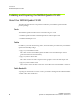
APPENDIX A OnBoard DIP Switch A P P E N D I X ONBOARD DIP SWITCH The Quadro FX SDI graphics card has an onboard dip switch, located on the SDI output card, that determines the default SDI operating mode. Subsequent software changes override these settings. SDI Output Card (7) Auto Switch (See Table A.3) (5-6) Sync Source (See Table A.2) (1-4) Output Video Format (See Table A.1) Figure 1.1 Onboard DIP Switch Positions NVIDIA Corporation Quadro FX 4500/5500 SDI User’s Guide – Version 2.
APPENDIX A OnBoard DIP Switch In the following tables, a “0” value corresponds to the “ON” switch position, and a “1” value corresponds to the “OFF” switch position. Table A.1 Output Video Format Switch Settings Switch Position 1234 Video Format 0000 1000 0100 1100 0010 1010 0110 1110 0001 1001 0101 1101 0011 1011 0111 1111 Reserved SMPTE 259 NTSC, 1440x487, 30/1.001 Hz, Interlace SMPTE 259 PAL, 1440x576, 25 Hz, Interlace SMPTE 260, 1920x1035, 30 Hz, Interlace SMPTE 260, 1920x1035, 30/1.