
Installation Manual

1) Read these instructions.
2) Keep these instructions.
3) Heed all warnings.
4) Follow all instructions.
5) Do not use this apparatus near water.
6) Clean only with a dry cloth.
7) Do not block any ventilation openings.
8) Install in accordance with the manufacturer’s instructions.
9) Do not install near any heat sources such as radiators, heat registers,
stoves or other apparatus (including DVRs) that produce heat.
10) Do not defeat the safety purpose of the polarized or
grounding-type plug. A polarized plug has two blades with one
wider than the other. A grounding type plug has two blades
and a third grounding prong. The wider blade or the third
prong are provided for your safety. If the provided plug does
not fit into your outlet, consult an electrician for replacement of
the obsolete outlet.
11) Protect the power cord from being walked on or pinched
particularly at plugs, convenience receptacles, and the point
where they exit from the apparatus.
12) Only use attachments/accessories specified by the
manufacturer.
13) Use only with cart, stand, tripod, bracket, or table
specified by the manufacturer, or sold with the apparatus.
When a cart is used, use caution when moving the
cart/apparatus combination to avoid injury from tipover.
14) Unplug this apparatus during lightning storms or when
unused for long periods of time.
15) Refer all servicing to qualified service personnel. Servicing
is required when the apparatus has been damaged in any
way, such as a power supply cord or plug is damaged, liquid
has been spilled, or objects have fallen into the apparatus, the
apparatus has been exposed to rain or moisture, does not
operate normally, or has been dropped.
16) The power switch on the rear of the apparatus shall remain
readily operable.
This installation should be made by a qualified service person
and should conform to all local codes.
WARNING -
Do not install the unit in an environment where the operating
ambient temperature exceeds 122° F (50° C). The ventilation should not be
impeded by covering the ventilation openings with items, such as newspapers,
table-cloths, curtains, etc. No naked flame sources, such as lighted candles
should be placed on the apparatus.
WARNING - Do not interconnect multiple outputs.
WARNING -
The apparatus shall not be exposed to dripping or
splashing and
no objects filled with liquids, such as vases, shall be placed on
the apparatus.
WARNING - Use only a Certified power cord and plug (coupler /
mains) assemblies for location installed.
WARNING - For safety, never put NVT signals in the same
conduit as high-voltage wiring.
Power Supply Cable Integrator
Hub Installation Manual
Models NV-4PS10-PVD and NV-16PS10-PVD
TM
IMPORTANT SAFETY INSTRUCTIONS
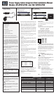
The NVT Power Supply Cable Integrator Hub combines a 1 Amp
/channel
†
power supply with pass through video and telemetry
data, for 4 to 16 cameras, all over UTP wire. Designed for
installation in the wiring/IDF telecom closet, or at the Control
/MDF room, the Hub consolidates connectivity via standard 4-pair
RJ45 EIA/TIA 568B compliant premises wiring and pinouts.
At the camera, Power, Video and Data connections are made using
the NV-216A-PV (power-video only) or the NV-218A-PVD
transceiver via an RJ45 connector and a single 4-pair cable.
Control/MDF room video connections are achieved with a single
4-pair RJ45 cable for each group of four cameras. Telemetry data
connections (if required) also achieved with another single 4-pair
RJ45 cable for each group of four cameras.
The NV-4PS10-PVD supports up to four cameras in a compact
wall- or desk-mount chassis. The NV-16PS10-PVD supports up to
16 cameras in a 1U wall- desk- or rack-mount chassis.
Wire Type
The Power Supply Cable Integrator Hub operates well with
Category 5 or better Unshielded Twisted-Pair (UTP) wire, 24
AWG (0,5mm) or thicker.
The video signal may co-exist in the same wire bundle as other
video, telephone, data, control signals, or low-voltage power. It is
also OK to run NVT signals near electromagnetic fields (in
accordance with National Electrical Code, and other local safety
requirements).
DO NOT USE individually shielded twisted pair. Overall
shielded, multi-pair (6pr +) is OK.
Do NOT use un-twisted wire.
Due to near-end crosstalk, do not send a transmit and a receive
signal in the same wire bundle. Exception: Up to 2,000ft (600m)
Category 5. Wire in underground conduit or wet locations must be
polyethelyne-jacketed, gel-filled.
Wire in plenum environments must be plenum-rated, per local codes.
RS-422, RS-485, and Up-the-Coax Pan/Tilt/Zoom telemetry
signals are supported.
Wire Distance
All measured distances include any coax in the path.
Wire resistance may be measured with an ohm-meter by shorting
the two conductors together at the far end, and measuring the
loop-resistance out and back.
Loop Resistance per 1000ft (300m)
24 AWG (0,53 mm) = 52 ohms
23 AWG (0,57 mm) = 42 ohms
22 AWG (0,64 mm) = 33 ohms
20 AWG (0,81 mm) = 21 ohms
19 AWG (0,91 mm) = 16 ohms
18 AWG (1,02 mm) = 13 ohms
Wire distances are limited to the minimum of:
POWER DISTANCE - the power loss along the wire from the
Power Supply Cable Integrator Hub out to the camera,
─ and ─
VIDEO DISTANCE - the video signal distance limit from
camera to the video receiver, and is dependent on the type of
receiver used.
†
NV-16PS10-PVD 10 Amps max, aggregate.
24 VAC
100 mA B&W Camera (2.4 Watts)
300 mA Color Camera (7.2 Watts)
1 Amp P/T/Z Camera (24 Watts)
899ft (274m)
1,134ft (346m)
300ft (91m)
378ft (115m)
90ft (27m)
113ft (35m)
2,098ft (640m)
2,645ft (807m)
699ft (213m)
862ft (269m)
210ft (64m)
265ft (81m)
Resultant Camera Voltage
2-pair 23 AWG (0,57mm)
2-pair 24 AWG (0,53mm)
2-pair 23 AWG (0,57mm)
2-pair 24 AWG (0,53mm)
2-pair 23 AWG (0,57mm)
2-pair 24 AWG (0,53mm)
21 VAC
21 VAC
Active or Passive Receiver Hub
Integrated PVD power with
New NV-4PS10-PVD or NV-16PS10-PVD
Camera Location and
Transmitter Connections
IDF | Telecom Room
and Midspan Connections
MDF | Control Room
and Receiver Connections
TO REDUCE THE RISK OF ELECTRICAL SHOCK, DO NOT
REMOVE COVER OR BACK. NO USER SERVICEABLE
PARTS INSIDE. REFER SERVICING TO QUALIFIED
SERVICE PERSONNEL.
WARNING: TO REDUCE THE RISK OF ELECTRICAL
SHOCK, DO NOT EXPOSE THIS APPARATUS TO
RAIN OR MOISTURE.
28 VAC
Power Supply Voltage Switch Setting
Power Distance
Wire distance between the Power Supply Cable Integrator and the
camera is dependent on the camera’s current draw. Please refer to
the Power Distance Guide below.
Video Distance
Wire distance between the camera through the Power Supply
Cable Integrator and on to the video receiver should not exceed:
Passive-to-Passive 750 ft (225m)
Passive-to-Active 3,000 ft (1km)
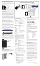
Connecting PVD at the Camera End
Use the NV-216A-PV for fixed cameras, or the NV-
218A-PVD for fixed or P/T/Z cameras. Install per the
instructions that come with the transmitting device using
4-pair wire and RJ45 connectors. NVT recommends the
use of factory-crimped RJ45 patch cables rather than
unreliable field-crimped RJ45s to connect between the
NVT device and an adjacent female RJ45 jack. Wiring
pinouts are:
Connecting PVD at the Power Supply Cable Integrator
Bring the 4-pair PVD cable from each camera back to the
location of the Power Supply Cable Integrator. NVT
recommends that an RJ45 Patch Panel be used here in
conjunction with RJ45 patch-cords. Use of these EIA/TIA
568B compliant practices allows for easy testing with an
RJ45 (LAN) tester, as well as moves and changes.
Connect the PVD signals into ports on the front of the
Power Supply Cable Integrator.
Connecting Power
CAUTION: Before applying power, set
voltage selection switch to proper input
line voltage.
Test your PVD connections with an RJ45 (LAN)
wiring tester prior to applying power.
Connect the IEC cable between the power inlet and a
grounded electrical outlet. Switch on the power
switch and observe the blue power LED.
Channel Power Status LEDs
For each channel, verify that its LED reports:
OFF: No camera connected (<50mA)
GREEN: Valid camera load detected
AMBER: Caution: Miswire possible
Detects that current in each of the four power
conductors is the same, allowing for the
detection of open conductors. Note that for
short wire runs, small mis-matches in
connector resistance may cause the LED to
show Amber. This condition is normal.
RED:
Over-current shutdown.
Check for shorts in the
wiring.
24 VAC
1
2
3
4
5
6
7
8
Wht/org
Org/wht
Wht/grn
Blu/wht
Wht/blu
Grn/wht
Wht/brn
Brn/wht
Video +
Video
-
Data +
Power
-
Power +
Data
-
Power +
Power
-
POWER DISTANCE GUIDE
NV-216A-PV
NV-218A-PVD
Camera
Camera
IP