
Installation Manual
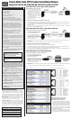


1. Connect the baseband Video signal
output from the camera to the male BNC
on the NV-216A-PV or NV-218A-PVD.
2. Connect the camera’s Power input to the
18AWG Power wires on the NV-216A-PV or
NV-218A-PVD. Verify wire distance,
camera load and wire resistance limit for
the maximum distance tha
t P
ower can
travel using Figure 2 below.
3.
Connect the 4-pair Cat-5 using the NV-216A-PV’s or NV-218A-PVD’s 8-pin RJ45 connector on the UTP run to the Equipment Room as
shown in Figure 3 below.
Connecting the Power-Video at the Equipment Room End
1. Connect the baseband Video input twisted pair to the screwless terminals adjacent to the RJ45 connector of the NV-218A-PVD, or using
the 8-pin RJ45 connector on the NV-216A-PV or NV-218A-PVD as shown in Figure 3 below.
2.
Connect the baseband Video signal output from the BNC pigtail on the NV-218A-PVD or the BNC of the NV-216A-PV directly to the Video monitor,
multiplexer, or DVR.
3. Connect Power via a Class II (SELV) low-voltage Power supply. NVT recommends the use of 18AWG solid wire. NVT also recommends
P
ower supplies with individually floating outputs.
1. Connect the baseband Video signal output
from the camera to the Male BNC pigtail
connector on the NV-218A-PVD.
2. Connect the camera’s Power input to the
screwless terminals marked P
ower on the
NV-218A-PVD. Verify wire distance,
camera load and wire resistance limit for
the maximum distance tha
t Power can
travel using Figure 2 below.
3. If the camera supports P/T/Z telemetry over RS-422 or RS-485, connect the camera’s Data terminals to the Data screwless terminals on the
NV-218A-PVD.
4. Connect the 4-pair Cat-5 using the 8-pin RJ45 connector on the UTP run to the Control end as shown in Figure 3 below.
Connecting the Po
wer
-Video-Data at the Equipment Room
1.
Connect the 4-pair Cat-5 from the camera end to the RJ45 connector on the NV-218A-PVD.
2. Connect the baseband Video signal output from the BNC pigtail on the NV-218A-PVD directly to the Video monitor, multiplexer or DVR.
3. Connect the control equipment data port to the screwless terminals marked data on the NV-218A-PVD.
4.
Connect the Power screwless terminals to a Class II (SELV) low-voltage Power supply. NVT recommends the use of 18AWG solid wire. NVT
also recommends Power supplies with individually floating outputs.
Power-Video-Data 4 or 16-Channel application
1.
Connect the baseband
Video signal output from
the camera to the male BNC on the NV
-216A-
PV or, in the case of a Data application, to the
NV
-218A-PVD male BNC pigtail.
2.
Connect the camera’s Power input to the
18AWG Power wires on the NV-216A-PV or the
NV
-218A-PVD. Verify wire distance, camera
load and wire resistance limit for the maximum
distance tha
t Power can travel. Verify the
wire/P
ower distance against Figure 2.
3.
If the camera supports P/T/Z telemetry over RS-422 or RS-485, connect the camera’s Data terminals to the Data screwless terminals on the
NV
-218A-PVD.
4.
Connect the 4-pair Cat-5 UTP using the 8-pin RJ45 connector on the UTP run to the Control end as shown in Figure 3 below.
1. Connect the baseband Video signal output from the camera
to the male BNC on the NV
-216A-PV or the NV
-218A-PVD.
2.
Connect the outputs of the independent power supply into
a
ppropriate camera power terminals on the NV-704J-PVD
as sho
wn in Figure 4 or NV-716J-PVD as shown in Figure 5.
Torque to 2in.-lbs. NVT recommends the use of 18AWG
solid conductor wire. NVT also recommends power supplies
with individually floating outputs.
3.
Connect the control end outputs via UTP using the 8-pin
RJ45 connectors for the NV
-704J-PVD as shown in Figure
4 or NV
-716J-PVD as shown in Figure 5 (details on page 2).
Measure Your Wire Distance
All NVT quoted distance specifications include any coax in the run. It is
recommended that the wire distance be measured to ensure that the
ca
pability of the NVT product is correct.
Wire should be Category UTP
cable.Low-voltage camera Power, Video, and RS-422 or RS-485 may
be sent within the same wire bundle. Do not run 24VAC or 28VAC in
the same wire bundle with other Telecom or Datacom signals.
Video Distance: Wire resistance may be measured with an ohm-
meter by shorting the two conductors together a
t the far end, and
measuring the loop-resistance out and back. See Figure 1.
Camera Power Distance: Different cameras draw different amounts
of current. It is important to make sure that the voltage-drop on the
wire allo
ws sufficient volta
ge for the camera to operate properly. A
camera voltage of 21VAC or greater is usually acceptable. Figure 2
shows typical wire distances for standard camera configurations.
Figur
e 1
Resistance per 1,000 ft (300 m) out and back
24AWG (0,5mm) = 52 Ohms per 1000ft (300m)
22AWG (0,6mm) = 32 Ohms per 1000ft (300m)
20AWG (0,7mm) = 20 Ohms per 1000ft (300m)
19AWG (0,8mm) = 16 Ohms per 1000ft (300m)
18AWG (1,0mm) = 13 Ohms per 1000ft (300m)
16AWG (1,3mm) = 8.2 Ohms per 1000ft (300m)
1) Read these instructions.
2) Keep these instructions.
3) Heed all warnings.
4) Follow all instructions.
5) Do not use this apparatus near water.
6) Clean only with a dry cloth.
7) Do not block any ventilation openings.
8) Install in accordance with the manufacturer
’s instructions.
9) Do not install near any heat sources such as radiators, heat
registers, stoves or other apparatus (including DVRs) that produce
heat.
10) Do not defeat the safety purpose of the polarized or
grounding-type plug. A polarized plug has two blades with one
wider than the other
. A grounding type plug has two blades and a
third grounding prong. The wider blade or the third prong are
provided for your safety
. If the provided plug does not fit into your
outlet, consult an electrician for replacement of the obsolete
outlet.
1
1) Protect the power cord from being walked on or pinched
particularly at plugs, convenience receptacles, and the point
where they exit from the apparatus.
12) Only use attachments/accessories specified by the
manufacturer
.
13) Use only with cart, stand, tripod, bracket, or table specified by
the manufacturer, or sold with the apparatus. When a cart is used,
use caution when moving the cart/apparatus combination to avoid
injury from tipover
.
14) Unplug this apparatus during lightning storms or when unused
for long periods of time.
15) Refer all servicing to qualified service personnel. Servicing is
required when the apparatus has been damaged in any way
, such
as a power supply cord or plug is damaged, liquid has been
spilled, or objects have fallen into the apparatus, the apparatus
has been exposed to rain or moisture, does not operate normally,
or has been dropped.
This installation should be made by a qualified service
person and should conform to all local codes.
W
ARNING - Do not install the unit in an environment
where the operating ambient temperature exceeds 120° F
(50° C). The ventilation should not be impeded by covering the
ventilation openings with items, such as newspapers, table-
cloths, curtains, etc. No naked flame sources, such as lighted
candles should be placed on the apparatus.
W
ARNING - Do not interconnect multiple outputs.
WARNING - The aparatus shall not be exposed to
dripping or splashing and no objects filled with liquids, such
as vases, shall be placed on the apparatus.
W
ARNING - Use only a Certified power cord and plug
(coupler / mains) assemblies for location installed.
W
ARNING - Power cord is regarded as main disconnect.
WARNING - The appliance coupler (power cord/mains)
shall remain readily operable.
WARNING - For safety, never put NVT signals in the same
conduit as high-voltage wiring.
WARNING - Do not restrict airflow around any active
powered NVT products.
TO REDUCE THE RISK OF ELECTRICAL SHOCK, DO
NOT REMOVE COVER OR BACK. NO USER
SER
VICEABLE P
ARTS INSIDE. REFER SERVICING
T
O QUALIFIED SERVICE PERSONNEL.
W
ARNING: T
O REDUCE THE RISK OF ELECTRICAL
SHOCK, DO NOT EXPOSE THIS
APPARATUS TO RAIN
OR MOISTURE.
IMPORTANT SAFETY INSTRUCTIONS
Power-Video-Data CCTV Product Installation Manual
Models NV-216A-PV
,
NV-218A-PVD, NV-704J-PVD and NV-716J-PVD
Power-Video Fixed camera single channel application
Po
wer and
Video at the Camer
a End
Power-Video-Data P/T/Z camera single channel application
Connecting Power-Video-Data at the Camera End
Power-Video-Data connection to the
NV-704J-PVD or NV-716J-PVD at the
Telecommunications Closet or IDF
Figure 3 Transceiver Pinouts & UTP Wire Colors
Figur
e 4
Control End Pinouts (NV
-704J-PVD)
Figure 2 Power Distance Charts
Figure 5 Control End Pinouts (NV-716J-PVD)
Connecting Po
wer-Video-Data at the Camera End