
Manual
NXG recommends the use of 16-gauge wire minimum. For wire options consult your retailer
or custom audio contractor
.
1. NXG
Architectural Speakers are designed to be installed in the ceiling or wall area between
studs. Using a stud finder, make sure you are between two studs. Tape the supplied template to
the wall and lightly trace around the inside with a pencil.
2. Cut the hole using your drywall saw. You may want to start with a small hole in the center of
the outline.
This will allow you to check for any obstructions that may exist behind the desired
location. CAUTION: Be certain electrical wiring, water pipes or heating ducts do not interfere in
the planned installation areas prior to drilling or cutting the wall.
3. Run speaker wire from your amplifier or speaker switching device to the speaker location.
4. Carefully remove the grille and inner grille backing. (Note: The open cell foam inner grille backing
is designed to hide speaker components from view and may be removed if desired.) If you like the
standard white finish of your NXG speakers, skip to step 5, but if if you want your speakers to blend
in with a colored wall or ceiling, now is the time to paint your speaker’s outer frame and perforated
grille. (Remove the foam inner grille backing and put it aside in a clean and dust free area for later
reinstallation if desired.) The speaker’s outer surface will accept ordinary latex wall paint or aerosol
spray paint. Because the speaker baf
fle surface behind the grille should remain unpainted, you will
need to cover this area with the supplied cardboard paint mask. Cover the speaker
’
s interior black
surface, woofer and tweeter. Paint the outer speaker frame and grille separately. (Grille painting hint:
Use a paint roller that is nearly out of paint to first paint the inside of the grille, then the outside. This
will avoid paint filling the grille perforations.)
5. Attach the wire to the input terminals on the rear of the speaker. Remember to maintain proper
polarity with the amplifier by attaching the positive (+) lead to the red terminal and the negative (-)
lead to the black terminal.
Congratulations on choosing NXG In-Ceiling
Loudspeakers. Like all NXG products, great
care has been taken in their design. Their
combination of advanced engineering and
state-of-the-art materials will provide you
with years of listening pleasure, while blending
smoothly into your home’s decor. Before you
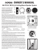
get started, it is a good idea to identify all the
parts and hardware (See Fig. 1).
FIG. 1
Cutout
Template
Speaker with self-contained
mounting clamps
Metal Grille with
foam inner backing
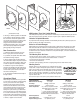
FIG. 2
NXG ceiling speakers can be used as rear
surround channels by mounting them
(1) on each side of, (2) just behind,
or (3) in back of the viewing position.
1
1
2
2
3
3
(Continued on reverse)
Where To Place Your In-Ceiling Speakers
Placement can make all the difference in how your speakers sound, and how easy they will be to
install. Carefully consider where your speakers should be positioned. For optimum performance,
speakers should be mounted to the left and right of the main listening area and a minimum of 8 to 10
feet apart (See Fig. 2). Avoid mounting speakers in stud cavities containing electrical wiring, heating
ducts, water pipes, etc. Make sure the ceiling materials are sturdy enough to support the weight of
the speakers.
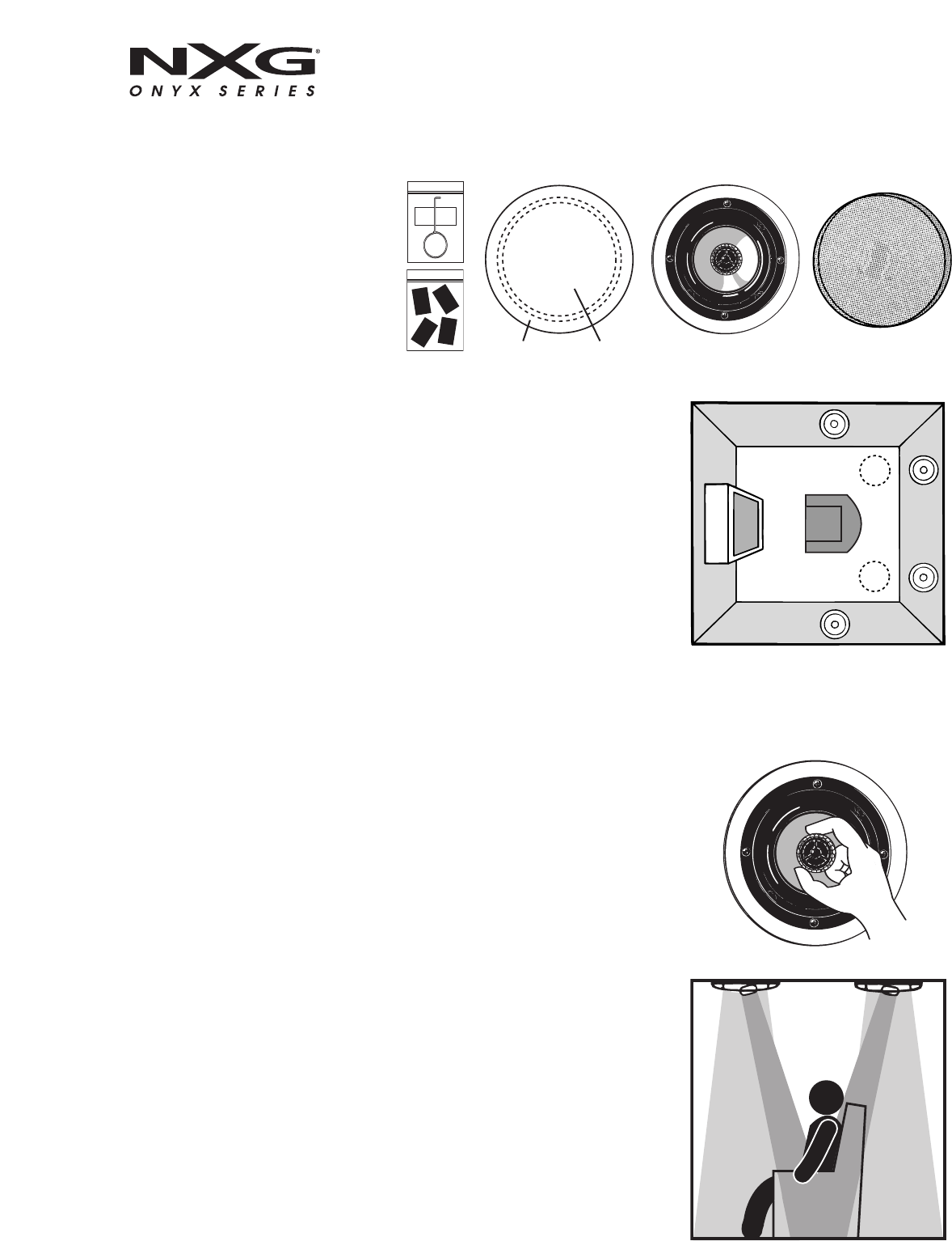
Adjustable Tilt-Swivel Tweeter Island (Fig. 3)
The tweeter island in the NXG ceiling speakers can be directed toward the listening area allowing
you to tailor the speaker's dispersion pattern to better fit the desired listening area. The overall
smoothest response is achieved with the tweeter island facing straight out; however, you may find
the sound more pleasing by aiming the tweeters toward a particular listening position. To adjust
the tweeter island direction, you can rotate the tweeter housing as shown in Fig. 3a.
Speaker Installation In Existing Construction (See Fig. 4 on reverse)
Once you have selected the location for your speakers, you are ready to install them.
You will need the following:
• Stud Finder • Drill & Drill Bits • Wire Cutter/Strippers • Speaker Wire
• Pencil • Phillips Screwdriver • Utility Knife or Drywall Saw • Masking Tape
FIG. 3
OWNER’S MANUAL
NX-C5.2-X, NX-C6.2-X Ceiling-Mount Speaker System
Grille
removal
tool
Black
grille
adhesive
Painting
Mask