
User Manual


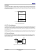


Table Of Contents
- 1 Introduction
- 2 Pin Configurations
- 3 CPU
- 4 Memory Organisation
- 5 System Clocks
- 6 Reset
- 7 Interrupt System
- 8 Wireless Transceiver
- 9 Digital Input/Output
- 10 Serial Peripheral Interface
- 11 Timers
- 12 Pulse Counters
- 13 Serial Communications
- 14 JTAG Debug Interface
- 15 Two-Wire Serial Interface
- 16 Four-Wire Digital Audio Interface
- 17 Random Number Generator
- 18 Sample FIFO
- 19 Intelligent Peripheral Interface
- 20 Analogue Peripherals
- 21 Power Management and Sleep Modes
- 22 Electrical Characteristics
- 22.1 Maximum Ratings
- 22.2 DC Electrical Characteristics
- 22.3 AC Characteristics
- 22.3.1 Reset and Voltage Brown-Out
- 22.3.2 SPI MasterTiming
- 22.3.3 Intelligent Peripheral (SPI Slave) Timing
- 22.3.4 Two-wire Serial Interface
- 22.3.5 Four-Wire Digital Audio Interface
- 22.3.6 Wakeup and Boot Load Timings
- 22.3.7 Bandgap Reference
- 22.3.8 Analogue to Digital Converters
- 22.3.9 Digital to Analogue Converters
- 22.3.10 Comparators
- 22.3.11 32kHz RC Oscillator
- 22.3.12 32kHz Crystal Oscillator
- 22.3.13 32MHz Crystal Oscillator
- 22.3.14 24MHz RC Oscillator
- 22.3.15 Temperature Sensor
- 22.3.16 Radio Transceiver
- Appendix A Mechanical and Ordering Information
- Appendix B Development Support

Jennic
© Jennic 2009 JN-DS-JN5148-001 1v2 19
Preliminary
5 System Clocks
Two system clocks are used to provide timing references into the on-chip subsystems of the JN5148. A 16MHz clock,
generated by a crystal-controlled 32MHz oscillator, is used by the transceiver, processor, memory and digital and
analogue peripherals. A 32kHz clock is used by the sleep timer and during the startup phase of the chip.
5.1 16MHz System Clock
The 16MHz system clock is used by the digital and analogue peripherals and the transceiver. A scaled version
(4,8,16 or 32MHz) of this clock is also used by the processor and memories. For most operations it is necessary to
source this clock from the 32MHz oscillator.
Crystal oscillators are generally slow to start. Hence to provide a faster start-up following a sleep cycle a fast RC
oscillator is provided that can be used as the source for the 16MHz system clock. The oscillator starts very quickly
and is typically 24MHz causing the system clock to run at 12MHz. Using a clock of this speed scales down the speed
of the processor and any peripherals in use. For the SPI interface this causes no functional issues as the generated
SPI clock is slightly slower and is used to clock the external SPI slave. Use of the radio is not possible when using the
24MHz RC oscillator. Additionally, timers and UARTs should not be used as the exact frequency will not be known.
The JN5148 device can be configured to wake up from sleep using the fast RC oscillator and automatically switch
over to use the 32MHz xtal as the clock source, when it has started up. This could allow application code to be
downloaded from the flash before the xtal is ready, typically improving start-up time by 550usec. Alternatively, the
switch over can be controlled by software, or the system could always use the 32MHz oscillator as the clock source.
5.1.1 32MHz Oscillator
The JN5148 contains the necessary on chip components to build a 32MHz reference oscillator with the addition of an
external crystal resonator and two tuning capacitors. The schematic of these components are shown in
Figure 9.
The two capacitors, C1 and C2, should typically be 15pF and use a COG dielectric. Due to the small size of these
capacitors, it is important to keep the traces to the external components as short as possible. The on chip
transconductance amplifier is compensated for temperature variation, and is self-biasing by means of the internal
resistor R1. The electrical specification of the oscillator can be found in section 22.3.13. Please refer to Appendix B
for development support with the crystal oscillator circuit.
XTALOUT
C2 C1
R1
XTALIN
JN5148
Figure 9: 32MHz Crystal Oscillator Connections
5.1.2 24MHz RC Oscillator
An on-chip 24MHz RC oscillator is provided. No external components are required for this oscillator. The electrical
specification of the oscillator can be found in section
22.3.14.