
User Manual
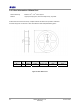
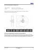
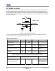
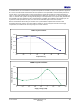
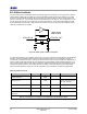
Table Of Contents
- 1 Introduction
- 2 Pin Configurations
- 3 CPU
- 4 Memory Organisation
- 5 System Clocks
- 6 Reset
- 7 Interrupt System
- 8 Wireless Transceiver
- 9 Digital Input/Output
- 10 Serial Peripheral Interface
- 11 Timers
- 12 Pulse Counters
- 13 Serial Communications
- 14 JTAG Debug Interface
- 15 Two-Wire Serial Interface
- 16 Four-Wire Digital Audio Interface
- 17 Random Number Generator
- 18 Sample FIFO
- 19 Intelligent Peripheral Interface
- 20 Analogue Peripherals
- 21 Power Management and Sleep Modes
- 22 Electrical Characteristics
- 22.1 Maximum Ratings
- 22.2 DC Electrical Characteristics
- 22.3 AC Characteristics
- 22.3.1 Reset and Voltage Brown-Out
- 22.3.2 SPI MasterTiming
- 22.3.3 Intelligent Peripheral (SPI Slave) Timing
- 22.3.4 Two-wire Serial Interface
- 22.3.5 Four-Wire Digital Audio Interface
- 22.3.6 Wakeup and Boot Load Timings
- 22.3.7 Bandgap Reference
- 22.3.8 Analogue to Digital Converters
- 22.3.9 Digital to Analogue Converters
- 22.3.10 Comparators
- 22.3.11 32kHz RC Oscillator
- 22.3.12 32kHz Crystal Oscillator
- 22.3.13 32MHz Crystal Oscillator
- 22.3.14 24MHz RC Oscillator
- 22.3.15 Temperature Sensor
- 22.3.16 Radio Transceiver
- Appendix A Mechanical and Ordering Information
- Appendix B Development Support

Jennic
88 JN-DS-JN5148-001 1v2 © Jennic 2009
Preliminary
B.2 32MHz Oscillator
The JN5148 contains the necessary on-chip components to build a 32 MHz reference oscillator with the addition of
an external crystal resonator, two tuning capacitors. The schematic of these components are shown in
Figure 53.
The two capacitors, C1 and C2, will typically be 15pF ±5% and use a COG dielectric. For a detailed specification of
the crystal required and factors affecting C1 and C2 see Appendix
B.1. As with all crystal oscillators the PCB layout is
especially important, both to keep parasitic capacitors to a minimum and to reduce the possibility of PCB noise being
coupled into the oscillator.
XTALOUT
C2 C1
R1
XTALIN
JN5148
Figure 53: Crystal oscillator connections
The clock generated by this oscillator provides the reference for most of the JN5148 subsystems, including the
transceiver, processor, memory and digital and analogue peripherals.
32MHz Crystal Requirements
Parameter Min Typ Max Notes
Crystal Frequency 32MHz
Crystal Tolerance 40ppm Including temperature
and ageing
Crystal ESR Range (Rm)
10Ω
60Ω
See below for more
details
Crystal Load Capacitance
Range (CL)
6pF 9pF 12pF See below for more
details
Not all Combinations of Crystal Load Capacitance and ESR are Valid
Recommended Crystal
Load Capacitance 9pF and max ESR 40 Ω
External Capacitors (C1 & C2)
For recommended Crystal
15pF
CL = 9pF, total external
capacitance needs to be
2*CL. , allowing for stray
capacitance from chip,
package and PCB