
Datasheet


9397 750 13117 © Koninklijke Philips Electronics N.V. 2004. All rights reserved.
Product data sheet Rev. 03 — 12 May 2004 12 of 17
Philips Semiconductors
74ALVC16245; 74ALVCH16245
16-bit bus transceiver with direction pin; 3-state
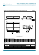
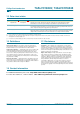
Test data is given in Table 11.
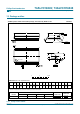
Definitions test circuit:
R
L
= Load resistor.
C
L
= Load capacitance includes jig and probe capacitance.
R
T
= Termination resistance should be equal to Z
o
of pulse generator.
Fig 8. Load circuitry for switching times.
Table 11: Test data
Supply
voltage
Input Load V
EXT
V
CC
V
I
t
r
, t
f
C
L
R
L
t
PLH
, t
PHL
t
PHZ
, t
PZH
t
PLZ
, t
PZL
< 2.7 V V
CC
2.0 ns 30 pF 500 Ω open GND 2 × V
CC
2.7 V − 3.6 V 2.7 V 2.5 ns 50 pF 500 Ω open GND 2 × V
CC
V
EXT
V
CC
V
I
V
O
mna616
D.U.T.
C
L
R
T
R
L
R
L
PULSE
GENERATOR