
Datasheet


Philips Semiconductors Product specification
74ALVT163732.5V/3.3V 16-bit transparent D-type latch (3-State)
1999 Oct 18
4
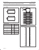
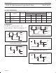
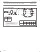
LOGIC DIAGRAM
E Q
D
nD0
nQ0
EQ
D
nD1
EQ
D
nD2
EQ
D
nD3
EQ
D
nD4
EQ
D
nD5
EQ
D
nD6
EQ
D
nD7
nQ1 nQ2 nQ3 nQ4 nQ5 nQ6 nQ7
nLE
nOE
SA00046
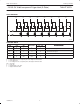
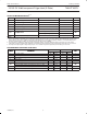
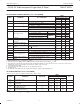
FUNCTION TABLE
INPUTS INTERNAL OUTPUTS
OPERATING MODE
nOE nLE nDx REGISTER nQ0 – nQ7
OPERATING
MODE
L
L
H
H
L
H
L
H
L
H
Enable and read register
L
L
↓
↓
l
h
L
H
L
H
Latch and read register
L L X NC NC Hold
H
H
L
H
X
nDx
NC
nDx
Z
Z
Disable outputs
H = High voltage level
h = High voltage level one set-up time prior to the High-to-Low E transition
L = Low voltage level
l = Low voltage level one set-up time prior to the High-to-Low E transition
NC= No change
X = Don’t care
Z = High impedance “off” state
↓ = High-to-Low E transition